SW-Stahl und Werkzeugvertriebs GmbH Tel. +49 (0) 2191 / 46438-0
F 56 essartS resukreveL ax +49 (0) 2191 / 46438-40
ed.lhatsws@ofni :liaM-E diehcsmeR 79824-D
Instruction Manual
BGS technic KG
Bandwirkerstr. 3
D-42929 Wermelskirchen
Tel.: 02196 720480
Fax.: 02196 7204820
mail@bgs-technic.de
www.bgstechnic.com
© BGS technic KG, Copying and further use not allowed
INSTRUCTION
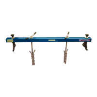
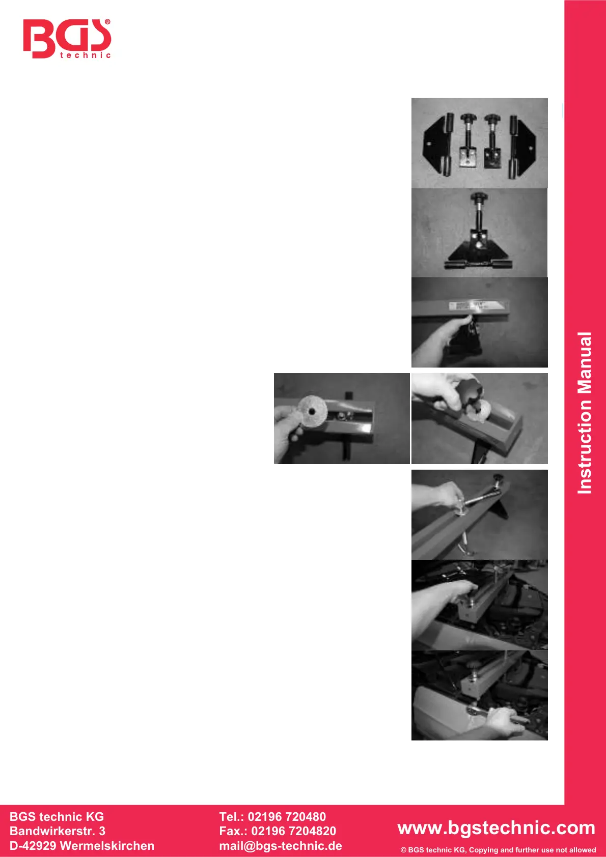
The engine support must be assembled before first use. Start with
assembling at the brackets. These consist of two parts and are
coupled with a screw.
Place the two support parts together and tighten the screws on the
side manually.
Insert the bolt of the bracket into each side of the engine support.
Put a washer on top of the bolt and screw
them in place with the help of hand nuts on
the engine support.
Mount the two holding screws in the middle collet of the engine
support, place a washer on the holding screws and tighten the large
wing nuts a few turns on the holding screws.
Place the engine support with the bracket either on the fender’s
screwing edge or rather on the fender’s welding edge. Make sure that
both hand-locking screws of the alignment are tight.
Adjust the angle of engine support and fix the setting with the lateral
screws.
When the two fixing screws for adjusting the inclination and the hand-
locking screws of the bracket are tightened, the chains are attached to
the appropriate places on the engine or gearbox and mounted onto the
holding screws.
Screw the wing nuts (holding spindles) until the chains are pulled
under tension and the entire load hangs on the chain. A dismantling of
e.g. gear or axle parts is now possible.
 Loading...