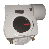
WGR – Worm Gear Reducer
Instruction and operating manual
© Copyright by BIFFI Italia. All right reserved MAN 684/Rev 5 Page 13
6 ASSEMBLING the WORM GEARBOX ONTO the VALVE
The worm gearbox is provided with an output flange and an insert (machined or not machined, based on Customer
requirements) for the coupling to the valve. The assembly position (orientation) of the valve/actuator (gearbox)
package must comply with the plant requirements.
To assemble the actuator onto the valve proceed as follows:
Check that the valve coupling dimensions of the flange and stem, or of the relevant extension, meet the worm
gearbox coupling dimensions.
Arrange the valve in the position related to the worm gearbox operation (for both butterfly valves and ball
valves the recommended position is OPEN).
Lubricate the valve stem with oil or grease in order to make the assembly easier: be careful not to contaminate
with lubricant the flange surfaces which have to be connected to transmit the actuator torque.
Clean the valve flange and remove anything that might prevent a perfect adherence to the worm gearbox
flange and especially all traces of grease.
If the insert supplied is not machined, remove it from the WGR output drive, machine it and reassemble it in
the WGR output drive.
Bring the worm gearbox to the recommended position (for both butterfly valves and ball valves the
recommended position is OPEN).
Clean the worm gearbox flange and remove anything that might prevent a perfect adherence to the valve
flange and especially all traces of grease.
Lower the actuator/WGR package onto the valve so that the WGR output drive couples with the valve stem
(for example, if the connection is made by key, the valve stem key groove must match with the WGR output
drive key groove). This coupling must take place without forcing and only with the weight of the actuator and
worm gearbox. When the worm gearbox output drive and the valve stem are connected, check the holes of the
valve flange. If they do not meet with the holes of the spool piece flange or the stud bolts screwed into them,
the worm gearbox output drive must be rotated until coupling is possible.
Tighten the nuts of the connecting stud bolts evenly with the torque prescribed in the table. If no different
materials are specified, the stud bolts must be made of ASTM A 320 Grade L 7 steel, the nuts must be made of
ASTM A 194 Grade 2 or better.


 To Next Page
 Loading...