IS200 Electro-Hydraulic Actuator Positioner
Orange Instruments Limited.
Drwg. No.: 1357-007 Issue : K Date : 07/10/2013 Page : 7 of 9
Iss c - Certificate number added. Iss D - Ta changed to -20 to +60
Iss E - Details of fail modes, timers and retrans. O/P added. Retrans. Signal barrier changed to KFD0-CC-Ex1
Iss F – Details of change in Max/min on & off times + addition of 10R in line with pos o/p –ve
Iss G – Stepping times range change to allow finer adjustment 15/11/2007
Iss H – CE Cert. of Conformity details added, Ta to –40degC, 60079:0,26 mods 25/06/2008
Iss J – Harmonised standards in C of C modified to meet current status 04/08/2008
Iss K - Markings changed to meet EN 60079-0:2012 02/10/2103
ATEX Certified Equipment - Change Authority ATEX Manager ONLY
Zone of Operation
The IS200 is an intrinsically safe device approved for operation in the following environment according to Specific Marking of
explosion protection:
Ex ia IIC T4 Ga (-40ºC Ta +60ºC) Ta = ambient temperature
IEC CENELEC North America
Zone 0 – continuous hazard present. Division 1
Gas Group – IIC (hydrogen, acetylene, carbon disulphide) Class 1A (Hydrogen)
Class 1B (acetylene)
Surface temperature – T4 135ºC – Ambient temperature -40ºC to +60ºC
Physical Description
Size – 70mm wide, 58mm high, 85mm deep
Weight – 0.25kg
Enclosure – Lexan (Top cover), Noryl (Base section)
Equipment rating – IP40
Specification
Note that all supplies and signals to and from safe areas MUST pass through appropriate Instrinsically Safe barriers before
connection to the IS200. See circuits on Page 7.
COMMAND SIGNAL INPUT
4-20mA nominal 240R input impedance
ANALOGUE POSITION OUTPUT SIGNAL
0-4.9V can be calibrated anywhere in this range – 10R resistor required in loop
FEEDBACK SIGNAL INPUT
Potentiometer 3-wire, any value greater than 200R
4-20mA nominal 240R input impedance
SWITCHED OUTPUTS x 3
PhotoMOS relays. Maximum load 130mA each.
INSTRUMENT SUPPLY
24V dc nominal safe area supply via an IS power supply
SOLENOID SUPPLY
24V dc nominal safe area supply via an IS power supply
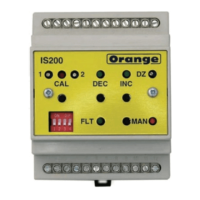
USER ADJUSTMENTS
DEC Button to close actuator in Manual
INC Button to open actuator in Manual
MAN Button to toggle auto/manual mode
CAL Button to selects Calibrate mode and store calibration data
DIP Switch 1 - Set stepping timers – DECREASE ON and OFF (Select fast-fail during normal operation)
DIP Switch 2 - Set stepping timers – INCREASE ON and OFF
DIP Switch 3 - Stepping timers setting mode select
DIP Switch 4 - Select stepping mode
Maximum OFF time 150 Seconds
DZ Potentiometer to set positioning dead zone - clockwise to increase
CAL1 Calibration adjustment and ON time for stepping mode
CAL2 Adjustment for OFF time for stepping mode
PERFORMANCE - the following applies to the IS200 only, characteristics of the feedback element, actuator system and
isolating barriers response will have additional effects.
Conversion 10 bit max normal conversion range (4-20mA) = 1 in 800.
O/P switch res. +/-1 bit theoretically, modified to up to +/-5% of span by dead band .
Accuracy (Theo.) 0.125% span based on conversion resolution of 1 in 800.
 Loading...