EasyManua.ls Logo

bihl+Wiedemann BWU2236 - User Manual

bihl+Wiedemann BWU2236
21 pages
Print Icon
To Next Page IconTo Next Page
Loading...
AS-i Safety Relay Output Module with Diagnostic Slave
1 EDM- and 2/1 safety inputs
User Manual
Revision date: 2011-05-30
...supports the requirements for AS-i Safety up to SIL3
Question and Answer IconNeed help?

Do you have a question about the bihl+Wiedemann BWU2236 and is the answer not in the manual?

Summary

EC Declaration of Conformity

Symbol Catalog

Abbreviations

Defines acronyms and abbreviations used in the manual for clarity.

General Remarks

Product Information

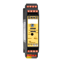
Identifies the specific Bihl+Wiedemann devices covered by this user manual.

Manual Functionality

Explains the manual's purpose for safe assembly, installation, and operation.

Target Audience

Identifies the intended users and professionals for this documentation.

AS-i Specification 3.0 Compliance

Confirms the module's design aligns with the AS-i specification version 3.0.

Safety

Qualified Personnel Requirements

Details the essential qualifications for staff involved in device installation and operation.

Device Application Area

Describes the module's role and integration within the AS-i Safety at Work system.

Correct Use Guidelines

Specifies the proper application and usage procedures for the safety relay module.

Product Disposal Instructions

Provides guidance for the safe and compliant disposal of the electronic device.

Product Description

AS-i Safety at Work System

Explains the AS-i Safety at Work system and its integration capabilities.

Key Features of AS-i Safety Output

Lists the principal characteristics and specifications of the safety output module.

Technical Specifications

Details the electrical, mechanical, and environmental specifications of the device.

Safety Relevant Data

Presents critical data related to the safety performance and integrity of the module.

Safe Input Parameter Overview

Summarizes the parameters relevant to the safe input functionality of the device.

Safe Output Parameter Overview

Summarizes the parameters relevant to the safe output functionality of the device.

Electrical Connection Diagram

Illustrates the wiring and terminal connections for the module.

Operating Interface Description

Explains the function of the device's switches, LEDs, and addressing jack.

LED Status Indicators

Details the meaning of each LED indicator on the module.

Maintenance

Verifying Safe Shutdowns

Outlines procedures for regular checks to ensure safe shutdown functionality.

Address Assignment

AS-i Address Types

Describes the three types of AS-i addresses the device supports: safety, input, diagnostic.

Programming Safety Output Address

Details the steps for programming the AS-i address for the safety output function.

AS-i Address Programming Details

Programming Safety Input Slave Address

Provides instructions for programming the AS-i address of the safety input slave.

Programming Diagnostic Slave Address

Explains the procedure to program the AS-i address for the diagnostic slave.

Safety Requirements

Safety Category 4 Environment Usage

Specifies requirements for operating the device within a Safety Category 4 environment.

Improving Function Availability

Offers recommendations to enhance the overall availability of the safety function.

Overview

The AS-i Safety Relay Output Module with Diagnostic Slave is a decentralized output module designed to safely control actuators within an AS-i Safety at Work (SaW) safety bus system. It integrates safety functions with diagnostic capabilities, making it suitable for applications requiring high safety integrity levels. This module is controlled by a Safety Monitor or a Gateway with an integrated Safety Monitor, which evaluates safe signals on the bus and manages the module's operation.

Function Description

The core function of the AS-i Safety Relay Output Module is to provide safe control of actuators by monitoring communication on a designated safe AS-i address. It features two series-connected positive-opening relays and two parallel-connected, galvanically isolated contact sets, ensuring redundant and reliable switching. The module is equipped with two safety potential-free contacts that can be connected to external safety devices. These contacts are continuously monitored for cross-connections, enhancing safety by detecting potential wiring faults.

A key characteristic of this module is its multi-address capability, offering three distinct AS-i address types:

  • Safety Output: This address is used for the safe control of actuators. The module listens to communication on this safe address and switches its outputs based on the received safe data. This ensures that safety-critical commands are processed with the required integrity.
  • Safety Input Slave: The module incorporates one safety input slave that monitors two contacts, S1 and S2. This allows for the integration of safety input devices, such as emergency stop buttons or safety gates, directly into the AS-i Safety at Work system.
  • Diagnostic Slave (AB Slave): A standard AS-i slave address is provided for diagnostic purposes and for switching under normal operating conditions. This allows for non-safety-related control and detailed diagnostics of the module's status and any potential faults, without interfering with the safety functions.

The module's design and functionality are certified to meet high safety standards, including EN 62061 (SIL 3) and EN 13849 (Performance Level "e"). It supports AS-i specification 3.0, while also maintaining full compatibility with earlier specifications (2.1 and 2.0).

Usage Features

The AS-i Safety Relay Output Module is designed for straightforward integration and operation within AS-i networks. Its operating interface includes switches for selecting different operational modes, facilitating addressing and configuration.

  • Mode Selection: The module features switches (ON, RUN, SEL, PRG) that allow users to select various operational modes. These modes include normal operation, addressing the safety slave, addressing the safety input slave, and addressing the diagnostic slave (AB address). This flexibility simplifies the initial setup and re-configuration processes.
  • Addressing: Programming the AS-i addresses for the safety output, safety input slave, and diagnostic slave is achieved using a hand-held addressing device or an AS-i Master. Specific switch settings are required for each addressing mode, guiding the user through the process. For instance, setting the switches to ON/PRG allows programming of the safety output address, while SEL/PRG is used for the safety input slave, and SEL/RUN for the diagnostic slave.
  • Input Monitoring: The module's safety input slave monitors the S1 and S2 contacts, which are supplied by a 24 V auxiliary voltage. These inputs are designed to connect normally open switches, and the module actively monitors them for cross-connections, providing an additional layer of safety.
  • Output Control: The module's relay outputs are capable of switching loads up to 3 A at 24 V DC-13 or 3 A at 230 V AC-15, making them suitable for controlling a wide range of actuators.
  • Diagnostic Indicators: A comprehensive set of LEDs provides visual feedback on the module's status, including power, fault conditions, output status, and input states. For example, green LEDs indicate power on, yellow LEDs show the state of safety inputs (S1, S2) and EDM input (1.Y1), and red LEDs signal AS-i faults or alarms. Specific flashing patterns and color combinations indicate various operational states, such as "output on," "restart inhibit," "output off," "waiting for reset of error condition," "internal error," and "output released but not switched on." This detailed feedback aids in quick troubleshooting and status monitoring.
  • External Device Monitoring (EDM): The module includes an EDM input (1.Y1) that monitors external devices, ensuring that safety circuits are functioning correctly. This input's state is also indicated by a dedicated yellow LED.
  • Electrical Connection: The module provides clearly labeled clamps for AS-i network connection (AS-i+, AS-i-), safety input clamps (S11, S12, S21, S22), safety output contact sets (1.13, 1.14, 1.23, 1.24), and auxiliary voltage supply (AUX+ext.in, AUX-ext.in). A programming jack is also available for configuration.
  • Power Supply Requirements: The AS-i power supply and the 24 V auxiliary supply must have isolation per IEC 60 742 and be able to handle momentary power interruptions of up to 20 ms. The maximum output voltage of the power supply must be less than 42 V in case of a fault, ensuring safe operation.

Maintenance Features

Maintenance of the AS-i Safety Relay Output Module primarily involves periodic verification of its safety functions and adherence to specified operating limits to ensure continued reliability and compliance with safety standards.

  • Regular Safety Shutdown Verification: The plant safety engineer is responsible for verifying the correct operation of the AS-i Safety Relay Output Module as part of the overall safety system. This verification should be performed at least once a year. It involves initiating associated safety-related sensors or switches and observing the reaction of the output circuits of the AS-i Safety Monitor. This ensures that the safe shutdown mechanism is functioning as intended.
  • Monitoring Activated Time and Total Operating Time: Users must check the maximum activated time and the total operating time of the module. These values are critical as they relate to the Probability of Failure on Demand (PFD) and the overall failure probability. This information is detailed in the "Safety relevant data" section of the manual.
  • Periodic System Checks: After reaching the projected maximum operating time (e.g., three, six, or twelve months, depending on the PFD value), the entire safety system must be checked for proper operation. This comprehensive check ensures that all components, including the AS-i Safety Relay Output Module, continue to meet safety requirements.
  • Manufacturer Check for Extended Usage: Upon reaching the projected total usage time (20 years), the device must be returned to the manufacturer for a thorough check to ensure its continued proper operation and safety integrity.
  • Turn-off Time Considerations: For improved availability of the safety function, the switching contacts should be turned off for at least 41 ms. This duration allows the Safety Monitor to correctly recognize the "INPUT OFF" state, especially depending on the number of slaves on the AS-i bus and the set monitoring component. Non-observance of this minimum off-time may limit the availability of the AS-i Safety Monitor, potentially leading to error states (e.g., with "TWO-CHANNEL POSITIVE OPENING" setting) or requiring a sufficient off-time before release (e.g., with "TWO-CHANNEL DEPENDENT" setting).
  • Disposal Information: The manual provides clear instructions regarding the disposal of the device, emphasizing that electronic waste is hazardous and must be disposed of in compliance with all local ordinances. It also confirms that the device does not contain batteries that need to be removed before disposal.

bihl+Wiedemann BWU2236 Specifications

General IconGeneral
Number of relay outputs2
Rated operating voltage Ue24 V DC
Rated operating current Ie per output2 A
AS-Interface voltage26.5...31.6 V
Connection type outputsScrew terminals
Protection classIP20
MountingDIN rail
Switching current2 A
Housing materialPlastic
Product typeRelay
Operating temperature-25...+60 °C
Storage temperature-40 °C to +85 °C
Contact materialAgNi