DOBIKON 1012 (Standard)
DOBIKON 1012
wurde 1974 von BIKON-Technik GmbH entwickelt.
Dieser Spannsatz geht nunmehr in seine neue 4.
Entwicklungsstufe / Generation.
DOBIKON 1012
was developed 1974 by BIKON-Technik GmbH.
Now this locking assembly goes to his new 4th
developing step / generation.
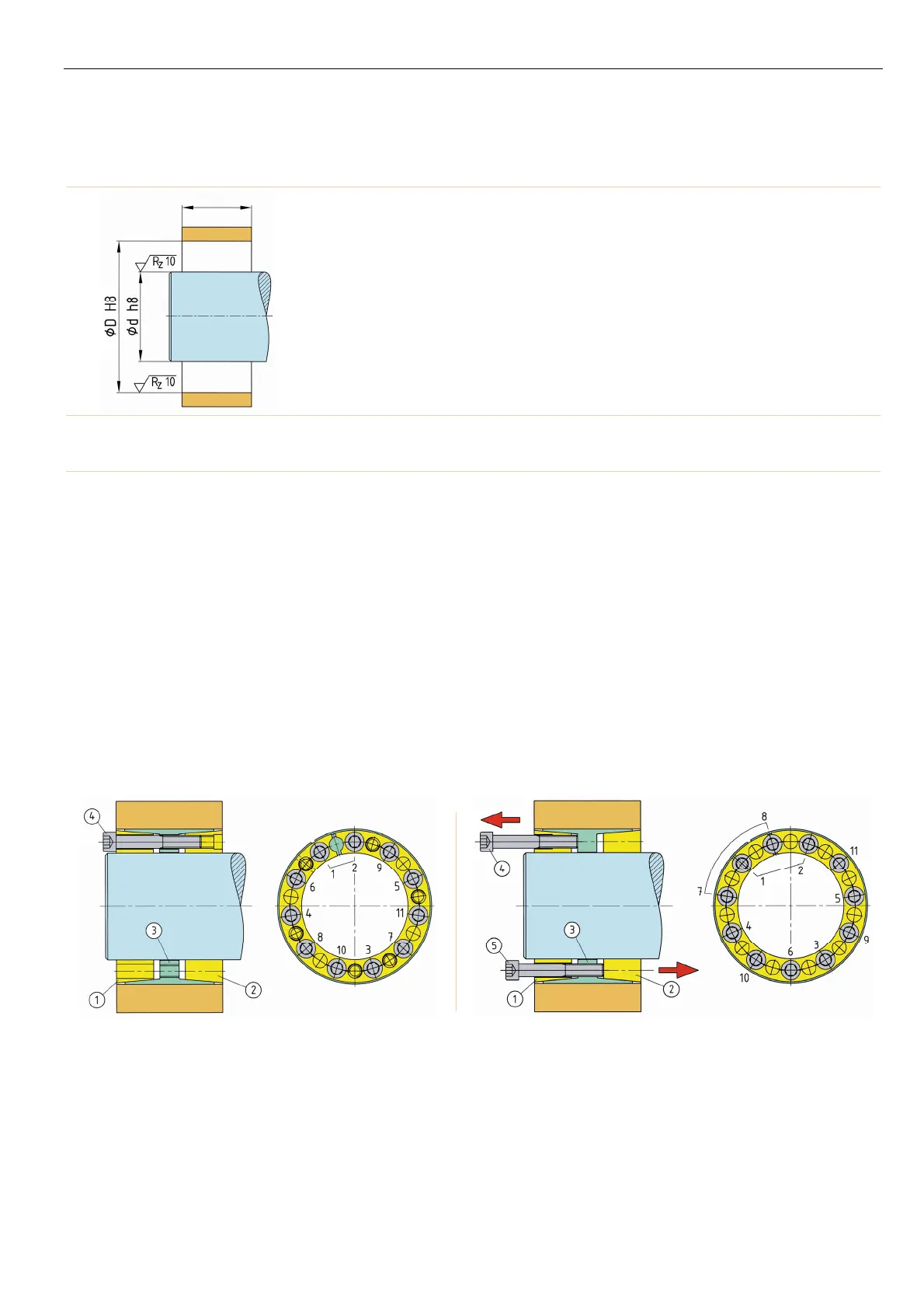
Einbauraum
Oberflächengüte und Passungen
Space
Surface quality and tolerances
selbstzentrierend self-centering autocentrante
DOBIKON 1012
è stato sviluppato dalla BIKON-Technik GmbH nel
1974.Questo dispositivo di bloccaggio ha ormai
raggiunto la sua quarta fase di sviluppo / generazione.
Spazio destinato all'inserimento
Qualità della superficie ed accoppiamenti
Montage
lle Schrauben (4) um einige Gewindegänge he-
rausdrehen und mindestens je 3 Schrauben in die
bdrückgewinde von Teil 1 und 3 einschrauben,
damit Teil 1 und Teil 2 von Teil 3 auf Abstand gehal-
ten werden - selbsthemmende Kegel !
Spannsatz geölt einsetzen.
Kein Molybden-Disulfid (MoS
2
) oder Fett verwenden !
Schrauben aus den Abdrückgewinden in die Gewin-
de des Druckrings (Teil 2) einschrauben.
Schrauben (4) gleichmäßig über Kreuz und in meh-
reren Stufen mittels Drehmomentschlüssel anziehen.
Schrauben links und rechts vom Schlitz hintereinan-
der anziehen.
Kontrolle
nzugsmoment T
A
der Schrauben (4) in der Reihen-
folge ihrer Anordnung prüfen. Der Anzug de
Schrauben und die Montage ist beendet, wenn sich
keine Schraube mehr anziehen lässt.
Spannsatz vor Verschmutzung schützen !
Installation
Release all screws (4) a few turns and transfer a
least 3 screws each to the release threads in part 1
and 3, to keep parts 1 and 2 spaced from part 3 -
self locking cones !
Lubricate locking assembly with oil.
Don't use molybdenum-disulfide (MoS
2
) or grease !
Take screws (4) out of the release threads and inser
them into the threads of part 2.
Tighten screws (4) evenly, alternating diagonally and
in progressive rounds of tightening with a torque
wrench, beginning each round with the next to the
slit.
Verification
Verify maximum tightening torque T
A
on all screws in
circumferential succession. Tightening and instal-
lation are completed, when none of the screws yields
any further.
Protect the locking assembly against soiling !
Montaggio
Svitare tutte le viti (4) di alcuni giri ed avvitarne almeno
3 nelle filettature di separazione dei particolari 1 e 3, in
modo da tenere distanziati i particolari 1, 2 e 3 – cono
autobloccante.
Lubrificare il dispositivo di bloccaggio con olio
prima di inserirlo.
Non utilizzare né bisolfuro di molibdeno (MoS
2
) né
grasso!
Estrarre le viti dalla filettatura di separazione ed
avvitarle nel filetto dell'anello di spinta (part. 2).
vvitare le viti (4) in diagonale progressivamente ed
uniformemente con una chiave dinamometrica.
Serrare le viti a destra e a sinistra del taglio, l'una
dopo l'altra.
Controllo
Verificare la coppia di serraggio T
A
delle viti (4)
procedendo in successione. Il lavoro di serraggio e di
montaggio sarà terminato quando tutte le viti saranno
state serrate.
Proteggere il dispositivo di bloccaggio dalla sporcizia!
≥ L2
Demontage
lle Schrauben (4) zum Lösen einige Gewindegänge
herausdrehen und soviel Schrauben wie Abdrück-
gewinde in der Spannhülse (3) und im Druckring (1)
vorhanden, herausdrehen und in die Abdrückgewin-
de einschrauben.
Lösen der Verbindung durch stufenweises, gleich-
mäßiges Anziehen der Schrauben (4 ) und (5) in den
bdrückgewinden. Schrauben links und rechts vom
Schlitz hintereinander anziehen.
Sollten die einzelnen Ringe zerlegt werden, muß die
Stellung zueinander markiert werden, um ein
falsches Zusammensetzen zu verhindern.
Removal
Release all screws for a few turns. Transfer as man
of them as there are release threads in parts 1 and 3
into these release threads.
Tighten screws (4) and (5) evenly, in progressive
rounds until the locking rings (1) and (2) come loose,
beginning each round with the next to the slit.
Should the single rings be disassembled, the posi-
tion must be marked to each other to prevent wrong
assembly.
Smontaggio
Svitare tutte le viti (4) di alcuni giri per allentare la
connessione e rimuovere le viti necessarie per lo
smontaggio avvitandole nelle filettature di
separazione poste negli anelli (1) e (3).
llentare la connessione avvitando le viti in
diagonale progressivamente ed uniformemente nelle
filettature di separazione.
Serrare le viti a destra e a sinistra del taglio, l'una
dopo l'altra.
Se fosse necessario smontare i singoli anelli,
segnare la loro reciproca posizione in modo da
evitare errori durante il montaggio.
Nabenberechnung
siehe Seite 53
oder kontaktieren Sie unsere technische Abteilung
Calculation of hub
see page 53
or contact our technical department
Calcolo del mozzo
vedere pagina 53
oppure contattate il nostro ufficio tecnico.
Rund- und Planlauf
Generelle Angaben zu Rund- und Planlauf sind nicht möglich.
Diese sind von den Anwendungen abhängig.
Kontaktieren Sie bitte unsere technische Abteilung.
Concentricity and run-out tolerance
General information concerning concentricity and run-out
tolerance are not possible. These depend on the application.
Contact please our technical department.
Concentricità e planarità
Non sono disponibili dati relativi alla concentricità ed alla
planarità, essendo questi dipendenti dal tipo di applicazione.
Vogliate contattare il nostro ufficio tecnico.
 Loading...