Do you have a question about the Bilstein B8 8100 and is the answer not in the manual?
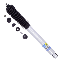
The Bilstein B8 8100 bypass shocks are high-performance suspension components designed to enhance the ride quality and handling of your vehicle. This instruction manual details the installation and maintenance procedures for both the left rear (driver) 25-284584 and right rear (passenger) 25-284591 B8 8100 shocks.
The B8 8100 bypass shocks are engineered to provide superior damping control by allowing the user to fine-tune the compression and rebound characteristics of the suspension. This adjustability is achieved through a proprietary bypass configuration that creates multiple damping zones. These zones enable the shock to offer different levels of resistance depending on the speed and magnitude of suspension movement, leading to optimized performance across various driving conditions. The gas-filled and highly pressurized design contributes to consistent damping performance and prevents cavitation, even during aggressive off-road use. The shocks are corner-specific, meaning each shock is designed for a particular corner of the vehicle to ensure proper fitment and performance.
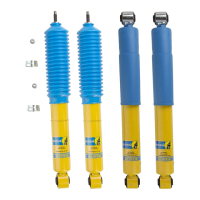
Installation of the B8 8100 bypass shocks requires specialized tools and expertise, and it is strongly recommended that installation be performed by a qualified suspension specialist. When replacing existing shocks, Bilstein recommends installing their shock absorbers as a complete set to maintain balanced suspension performance. The shocks are intended for specific applications as outlined in the application guide, and any deviation from this intended use may lead to serious injury or death.
The installation process begins with the removal of the existing shock. Users should inspect the original lower shock bolt/washer for any damage or wear, replacing them if necessary. A key feature of the B8 8100 installation is the Anti Rotation Pin and Anti Rotation Plate system. The Anti Rotation Pin is inserted into a specific frame hole, secured with a washer and Nylock, and then torqued to 7 ft-lb (10 Nm). The Anti Rotation Plate slides over the threaded pin and engages a D-ring boss at the base of the pin, preventing the shock from rotating and potentially contacting other vehicle components like the E-Brake cable.
The lower bushing and an appropriate alignment washer (selected based on the vehicle's year) are then slid over the threaded pin. The lower shock mount is installed, and the OE lower shock bolt/washer is threaded in until snug but not fully tightened. The shock is then compressed, and the threaded pin is guided through the chassis mount, ensuring the Anti Rotation Plate captures the Anti Rotation Pin and the alignment washer is centered.
The upper bushing and a concave washer (installed concave side up) are slid onto the threaded pin, followed by a flange locknut. This locknut is torqued to 20 ft-lb (27 Nm). After securing both upper and lower shock mounts, it's crucial to verify that the Anti Rotation Pin does not contact the Anti Rotation Plate or shock body. If contact occurs, the Nylock should be loosened, the pin adjusted slightly forward to create a small gap (~1/16"), and then re-torqued.
The reservoirs, an integral part of the bypass shock system, require a separate mounting procedure. For 4Runner and GX460/470 models, specific plastic pieces may need to be removed to access frame holes for reservoir mounting. The reservoir clamp is mounted to the reservoir mount plate using flat head screws, torqued to 16 ft-lb (22 Nm). A Nylock and socket head cap screw are partially installed into the reservoir clamp, allowing the reservoir to be slid through.
For vehicles with 10mm through holes in the frame, threaded inserts must be installed. This involves using a hex head cap screw, washer, serrated flange nut, and a 1/2" box end wrench to set the threaded insert firmly into the frame. Once the threaded inserts are in place (or if the frame holes are already threaded M8x1.25), the reservoir/bracket assembly is mounted to the frame using either flange head cap screws (for threaded holes) or hex head cap screws with washers (for threaded inserts). These fasteners are torqued to 18 ft-lb (25 Nm) or 14 ft-lb (19 Nm), respectively. The reservoir is positioned to ensure approximately 1/4" clearance from the exhaust hanger bracket and fender. Finally, the socket head cap screw on the reservoir clamp is tightened to 6 ft-lb (8 Nm).
Hose clamp installation involves placing a loop clamp around the hose and mounting it to the frame using either a flange head cap screw (for threaded holes) or a hex head cap screw (for threaded inserts), torqued to 14 ft-lb (19 Nm). For KDSS models on the left side, an existing flange head cap screw is used. After all components are installed, any removed plastic panels are re-installed. With the vehicle back on the ground, the OE lower shock bolt/washer is tightened to factory specifications, completing the installation.
The B8 8100 bypass shocks come with a factory setting of 5 full turns out from fully closed for rebound and 6 full turns out from fully closed for compression. Adjustments can be made using an Allen key. To adjust, loosen the jam nut from the bypass adjuster housing, then rotate the Allen key: clockwise to increase damping and counter-clockwise to decrease damping. After adjustment, the jam nut must be tightened against the bypass adjuster housing while holding the Allen key to prevent rotation. It may be necessary to hold the bypass adjuster housing with a wrench during this process.
The proprietary Bilstein zinc-plated finish on the B8 8100 bypass shocks requires periodic servicing to maintain its luster, especially in moist climates. A protective coating, such as wax or lubricating oil, should be applied regularly to prevent tarnishing. This finish is not covered under warranty.
It is normal to hear a slight audible clicking noise during compression and rebound strokes, particularly during low-velocity events. This sound is a characteristic of the internal check pistons opening and closing to create the externally adjustable compression and rebound zones and does not indicate a malfunction.
The Anti Rotation Pin (BOM item #1) and Anti Rotation Plate (BOM item #4) are considered wear items. These components should be inspected for excessive signs of wear every 20,000 miles and replaced as needed to ensure proper function and prevent potential damage to the shock or other vehicle components.
After installing any Bilstein product, it is essential to have the suspension caster and camber checked and/or adjusted to comply with the vehicle manufacturer's specifications. Additionally, the load-dependent brake compensator and the anti-lock brake system must be checked and/or reset according to the vehicle manufacturer's specifications. Finally, the headlight aim should be checked and adjusted to ensure proper visibility and safety.
For any service needs related to your B8 8100 bypass shocks, customers are directed to contact Thyssenkrupp Bilstein of America.
| Type | Shock Absorber |
|---|---|
| Series | B8 8100 |
| Technology | Monotube |
| Adjustability | Non-adjustable |
| Body Material | Steel |
| Piston Diameter | 46 mm |
| Extended Length | Varies by application |
| Collapsed Length | Varies by application |
| Warranty | Limited lifetime |
| Application | Performance |
| Finish | Zinc Plated |
| Gas Pressure | Nitrogen charged |