18 | Chapter 2: Hardware installaon
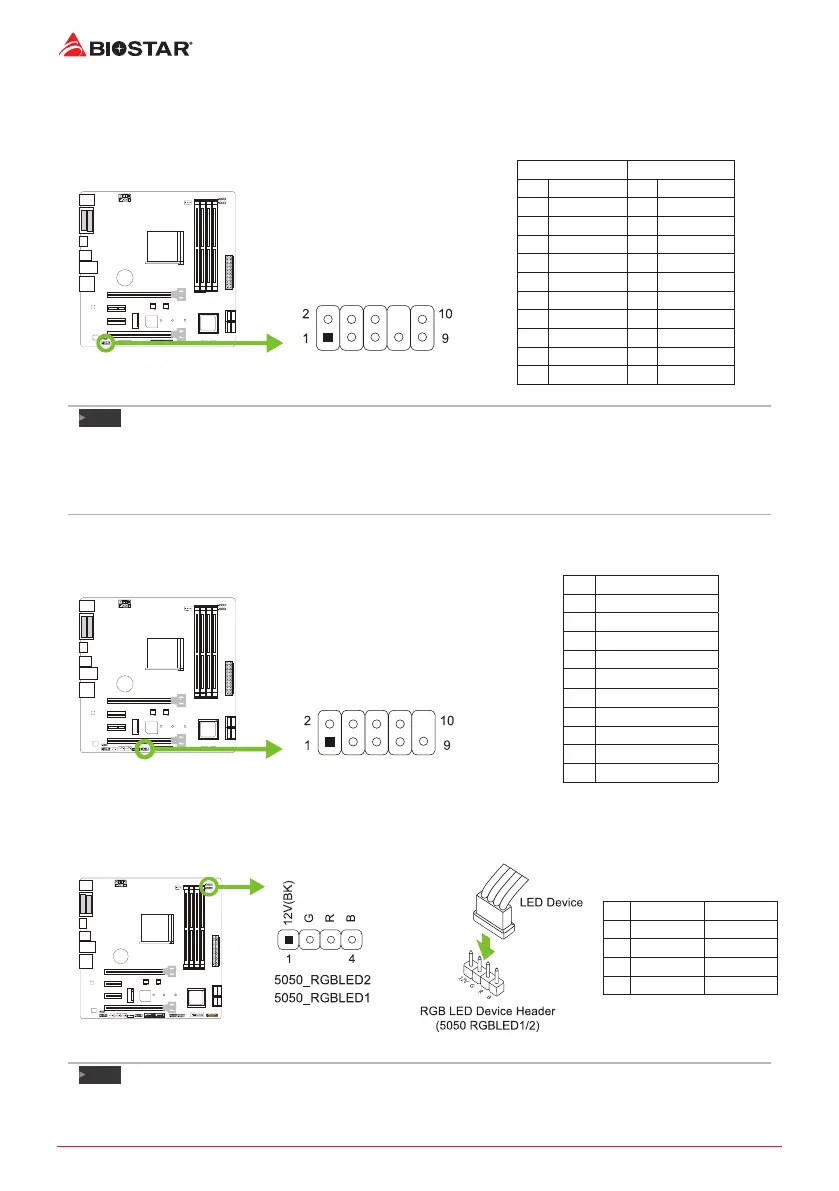
F_AUDIO1: Front Panel Audio Header
This header allows user to connect the chassis-mount front panel audio I/O which supports HD
and AC’97 audio standards.
HD Audio AC’97
Pin Assignment Pin Assignment
1 Mic Le in 1 Mic In
2 Ground 2 Ground
3 Mic Right in 3 Mic Power
4 GPIO 4 Audio Power
5 Right line in 5 RT Line Out
6 Jack Sense 6 RT Line Out
7 Front Sense 7 Reserved
8 Key 8 Key
9 Le line in 9 LFT Line Out
10 Jack Sense 10 LFT Line Out
Note
»
Itisrecommendedthatyouconnectahigh-denionfrontpanelaudiomoduletothisconnectorto
availofthemotherboard’shighdenionaudiocapability.
»
Pleasetrytodisablethe“FrontPanelJackDetecon”ifyouwanttouseanAC’97frontaudiooutput
cable.ThefunconcanbefoundviaO.S.AudioUlity.
J_COM1: Serial Port Connector
The motherboard has a serial port header for connecng RS-232 Port.
Pin Assignment
1 Carrier detect
2 Received data
3 Transmied data
4 Data terminal ready
5 Signal ground
6 Data set ready
7 Request to send
8 Clear to send
9 Ring indicator
10 Key
5050_RGBLED1/2: RGB LED Device (5050 SMD) Header
This header providers 12V power and RGB control pins for RGB LED Device (5050 SMD).
Pin Cable Color Assignment
1 12V (Black) VCC12
2 G (Green) LED_GREEN
3 R (Red) LED_RED
4 B (Blue) LED_BLUE
Note
»
EnsureproperpinconnecngtoyourLEDdevice,wrongconneconmaydamageyourLEDdeviceor
motherboard.
 Loading...