4
*Versions with automatic reset have this function integrated in the circuit
Housing DIN ABS, grey/black
Protection class-Enclosure IP30 (EN 60529)
Protection class-Clearance IP54 (EN 60529)
Weight max. 250 gramm (depending on type)
Power Supply 24 VACDC ±10%
acc. to EN60204-1 115 VAC ±10%
(depending on type) 230 VAC ±10%
Frequency Range 50/60 Hz (45–66 Hz)
Power consumption max. 5 VA
Duty Cycle 100%
Fastening 35 mm mounting rail
Safety Output Relay
Utilization category AC-1: 250 V/2 A/500 VA, approx. 300’000 switchings
acc.to EN60947-4-1** DC-1: 24 V/2 A/48 W, approx. 700’000 switchings
Utilization category AC-15: 250 V/2 A/500 VA, approx. 130’000 switchings
acc.to EN60947-5-1** DC-13: 24 V/2 A/48 W, approx. 70’000 switchings
(DC13: 6 switchings/ minute)
Contacts positively driven relays, AgCuNi
Operating Life mechanical 50 million switchings
Fuse Protection
acc. to EN60947-5-1 2 A slow
Status Relay
Switching Capacity** 24VDC/1A, resistive load
30VAC/1 A, resistive load
Indicators
Operation Green
Error Red (sensor resp. system error)
Safety Switch-off Yellow (sensor)
Reaction Time
Safety Output Relay < 50 ms
Temperature Range
Operation –20°C to +55°C
Storage –20°C to +80°C
Humidity max. 80% relative (no condensation allowed)
The correct functioning of the safety system must be checked periodically (monthly or accord-
ing to overruling regulations). The sensor and wiring connections must also be checked for
mechanical damage.
Proceed as follows if the function is not assured based on the wiring in the circuit diagram and
both yellow or red LEDs light up at the same time:
1. Press reset button (min. 1 sec.)
2. Check all sensors to determine if activated or damaged
3. Check sensor resistance on terminals 1/2 and 3/4 (8.2 kOhm)
4. Repeat commissioning
There is a unit fault if both red LEDs continue to light up afterwards.
Return the unit for
checking.
If only one yellow or red LED lights up Return the unit for checking.
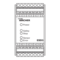
12
13
15
16
7
8
10
9
4
3
2
1
Sensor 1
Sensor 2
6
5
*
Terminal Terminal
1 Signal Sensor 1 9 Supply Voltage
2 Signal Sensor 1 10 Supply Voltage
3 Signal Sensor 2 11 –
4 Signal Sensor 2 12 Safety Output Relay 1
5 External Reset 13 Safety Output Relay 1
6 External Reset 14 –
7 Status Relay 15 Safety Output Relay 2
8 Status Relay 16 Safety Output Relay 2
**If not mentioned ratings are required, ask for them at the manufacturer
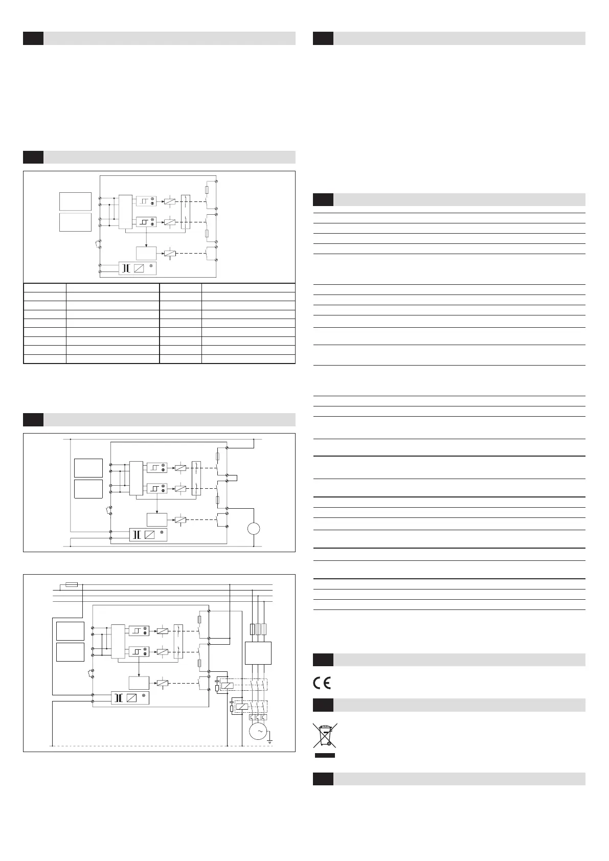
Wiring example for a one phase drive without control relay
12
13
15
16
7
8
10
9
6
5
4
*
3
2
1
Sensor 1
Sensor 2
M
N
P
Wiring example of a three-phase drive with control relay
1)
Note: the contactors K1 and K2 must be designed in a way that welding of the contacts is
recognized by K1 and K2 and does not lead into a loss of safety
12
13
1)
1)
15
16
7
8
10
9
6
5
4
*
3
2
1
Machine
control
F2–4
Sensor 1
Sensor 2
L1
K1
K2
M
3
F1
L2
L3
N
Block Diagram and Connection6
Technical data9
Control of External Contactors7
Periodical Checks and Fault Finding8
EU Declaration of Conformity10
WEEE11
Contact12
Devices with this symbol must be treated separately during disposal. This must be
done in accordance with the laws of the respective countries for environmentally
sound disposal, processing and recycling of electrical and electronic equipment.
BBC Bircher Smart Access, BBC Bircher AG
Wiesengasse 20, CH-8222 Beringen, www.bircher.com
See attachment
Designed in Switzerland / Made in EU
• The maximum length of the sensor with cable must not exceed 50 metres
• Maximum surface area 5 m
2
• If multiple sensors are used, they have to be connected in series
• The last sensor equipped with resistor 8.2 kOhm
• If only one sensor input is used channel 2 must be jumpered (provided resistance
8,2 kOhm ±1%), otherwise a fault signal is generated
Connection5
Subject to change without notice
 Loading...