16 KB-520-6
4 Electrical connection
4.1 General recommendations
The electrical accessory is in accor -
dance with the EC Low Voltage
Directive 73/23/EEC (CE 96).
The electrical installation is to be car-
ried out according to the wiring dia-
gram. Observe the safety standards
EN 60204, EN 60335 and national
safety regulations.
For the dimensions of the motor con-
tactors, cables and fuses :
Attention!
Maximum operating current or
max. power consumption of the
motor should be the base.
Con tac tor selec tion:
accord ing to oper a tion al cat e -
gory AC3.
• Voltage and frequency data on the
name plate should be compared to
the electrical supply data. The
motor may only be connected when
these coincide.
• Wire the motor terminals according
to the indications on the terminal
box cover.
4 Raccordement élec tri que
4.1 Indications géné ra les
Les accessoires électriques correspon-
dent à la Directive CE Basse Tension
73/23/CEE (CE 96).
Réaliser l’exécution de l’installation élec -
tri que confor mé ment au sché ma de prin -
ci pe. Respecter en les nor mes de sécu ri -
té EN 60204, EN 60335 et les pres crip -
tions de sécu ri té loca les.
Pour le dimen sion ne ment des contac -
teurs de moteur, des câbles d'alimen -
tation et des fusi bles,
Attention !
Le cou rant de ser vi ce maxi mal resp.
la puis san ce absor bée max. de
moteur sont à pren dre en consi dé -
ra tion.
Selection des contacteurs:
d’après catégorie d’utilisation AC3.
• Com pa rer les indi ca tions de ten sion et
de fré quen ce sur la pla que signa lé ti -
que avec les don nées du réseau. Le
moteur ne peut être rac cordé que s'il y
a concor dan ce.
• Rac cor der les bor nes du moteur con -
for mé ment aux instructions se trouvant
sur le couvercle de la boîte de raccor-
dement.
4 Elektrischer Anschluss
4.1 Allgemeine Hinweise
Das elektrische Zubehör entspricht
der EU-Nieder span nungs richtlinie
73/23/EWG (CE 96).
Elektrische Anschlüsse gemäß
Prinzipschaltbild ausführen.
Sicherheits nor men EN 60204,
EN 60335 und natio nale Schutz -
bestim mungen berück sichtigen.
Bei der Dimensio nie rung von Motor -
schützen, Zuleitungen und Siche run -
gen:
Achtung!
Maximalen Betriebsstrom bzw.
maximale Leistungsaufnahme
des Motors zugrunde legen.
Schütz auslegung:
nach Gebrauchskategorie AC3.
• Spannungs- und Frequenzangaben
auf dem Typschild mit den Daten
des Stromnetzes vergleichen. Der
Motor darf nur bei Über ein stimmung
angeschlossen werden.
• Motorklemmen gemäß Anweisung
auf dem Deckel des Anschluss -
kastens anschließen.
L
N
1 2
1 4
1 1
R e l a i s m a x
2 , 5 A 2 5 0 V
3 0 0 V A
R e s e t
S t e u e r s t r o m
C o n t r o l c i r c u i t
C i r c u i t d e c o m m a n d e
B 1
B 2
2 1
1
S U
S U
2
S E - B 2
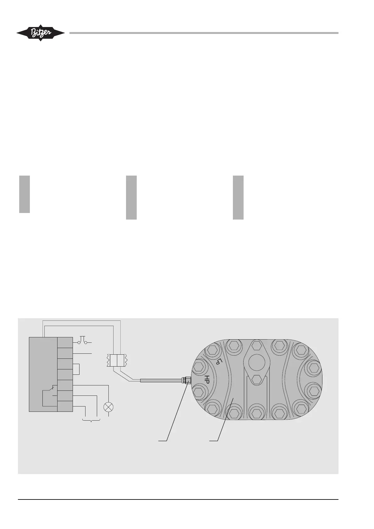
Abb. 10 Druckgas-Temperaturfühler
bei Anlaufentlastung
Fig. 10 Discharge gas temperature
sensor with start unloading
Fig. 10 Sonde de température du gaz au
refoulement avec SU
Légende
1 Sonde de température du gaz de refou-
lement
2 Tête de culasse du démarrage à vide
Legend
1 Discharge gas temperature sensor
2 Start unloading cylinder head
Legende
1 Druckgastemperatur-Fühler
2 Anlaufentlastungs-Zylinderkopf