Rev. 1.00
- 3 -
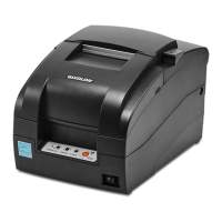
SRP-275II
4. Hardware ....................................................................................................................................................50
4-1 Wiring Diagram ...................................................................................................................................... 50
4-1-1 Main board wiring diagram.............................................................................................................. 50
4-1-2 SUB wiring diagram ........................................................................................................................51
4-2 Block Diagram........................................................................................................................................52
5. Disassembly and Assembly .....................................................................................................................53
5-1 SMP715 Printer mechanism unit Sub-assembly ................................................................................... 53
5-1-1 Frame-main caulking assy ..............................................................................................................53
5-1-2 Ribbon-feeder assy.........................................................................................................................53
5-1-3 Lever-ribbon-feeder assy................................................................................................................54
5-1-4 Lever-tension assy..........................................................................................................................54
5-1-5 Carriage head assy.........................................................................................................................55
5-1-6 Head-cover assy .............................................................................................................................55
5-1-7 Frame basket-A assy ......................................................................................................................56
5-1-8 Frame basket-C assy......................................................................................................................57
5-1-9 Frame-holder basket-L assy ........................................................................................................... 58
5-1-10 Frame-holder basket-L caulking assy...........................................................................................58
5-1-11 Frame-holder basket-R caulking assy ..........................................................................................58
5-1-12 Frame-housing cutter lower assy..................................................................................................59
5-1-13 Cutter lower assy ..........................................................................................................................59
5-1-14 Frame-rotator assy........................................................................................................................60
5-1-15 BMS-B assy ..................................................................................................................................61
5-1-16 BMS assy......................................................................................................................................61
5-1-17 Holder platen assy ........................................................................................................................62
5-2 SMP715 Printer mechanism unit Main-assembly..................................................................................63
5-2-1 Main-assembly A ............................................................................................................................63
5-2-2 Main-assembly B ............................................................................................................................64
5-2-3 Main-assembly C ............................................................................................................................65
5-2-4 Main-assembly D ............................................................................................................................66
5-2-5 Main-assembly E (for SMP715A type)............................................................................................67
5-2-6 Main-assembly E (for SMP715C type) ...........................................................................................68
5-3 Auto cutter unit assembly ......................................................................................................................69
5-3-1 AC timing belt assy .........................................................................................................................69
5-3-2 AC upper frame caulking assy ........................................................................................................69
5-3-3 AC upper cutter guide assy.............................................................................................................70
5-3-4 AC upper cutter assy ......................................................................................................................70
5-3-5 AC motor assy.................................................................................................................................71
5-3-6 AC motor sub assy..........................................................................................................................71
5-3-7 PCB-AC assy ..................................................................................................................................71
5-3-8 Main assy ........................................................................................................................................72
5-4 SRP-275II Whole unit Sub-assembly ....................................................................................................73
5-4-1 Cover base assy .............................................................................................................................73
5-4-2 Switch-paper near end assy ...........................................................................................................74
5-4-3 Switch-paper end assy....................................................................................................................74
5-4-4 Cover middle assy ..........................................................................................................................75
5-4-5 Switch-cover open assy..................................................................................................................76
5-4-6 Switch-paper near end -W assy......................................................................................................76
5-4-7 Bracket PCB assy ...........................................................................................................................77
5-4-8 Serial interface assy........................................................................................................................78
5-4-9 cover front-A assy ...........................................................................................................................78
5-5 SRP-275II Whole unit Main-assembly...................................................................................................79
5-5-1 Main-assembly A (for SRP-275IIA type).........................................................................................79
5-5-2 Main-assembly A (for SRP-275IIC type).........................................................................................81
5-5-3 Main-assembly B ............................................................................................................................83
5-5-4 Main-assembly C ............................................................................................................................85
5-5-5 Main-assembly D ............................................................................................................................86
 Loading...