Do you have a question about the Black Box ME475A-R2 and is the answer not in the manual?
Lists the key capabilities and specifications of the ME475A-R2 modem.
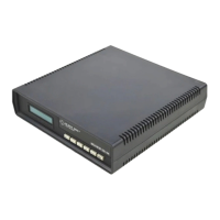
Provides an overview of the ME475A-R2 modem's function and operation.
Explains the use of 24 external DIP switches for modem configuration.
Details S1 DIP switch settings for data rate, clock source, mode, and carrier control.
Details S2 DIP switch settings for word length, signaling rate, RTS/CTS delay, and mode selection.
Details S3 DIP switch settings for input impedance, loopback, and anti-stream control.
Describes how to install the modem using a two-wire connection.
Details how to install the modem using a four-wire connection.
Explains setting up the modem for four-wire multipoint applications.
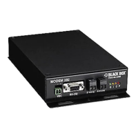
Describes connecting the modem to RS-232 devices.
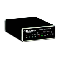
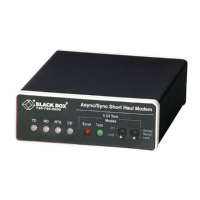
Explains the function of the six front panel LEDs indicating modem status.
Describes the functions of the "Error" indicator LED.
Details the function of the anti-streaming error indicator.
Outlines the steps for powering up the modem and expected LED conditions.
Introduces the V.54 test modes for evaluating modem and link conditions.
Details how to use the V.52 Bit Error Rate test independently.
Describes the procedure for powering down the modem.
Specifies the synchronous/asynchronous and 2-wire/4-wire transmission formats.
Details the RS-232 and twisted pair interfaces supported by the modem.
Specifies the type and gauge of transmission lines supported.
Lists the switch-selectable synchronous and asynchronous data rates.
Describes the available clocking options: internal, external, or receive recover.
Details carrier control and RTS/CTS delay settings.
Lists the supported applications: point-to-point or multipoint.
Describes the bi-color LED indicators for various signals.
Specifies the anti-stream timer settings and tolerance.
Details V.52 and V.54 diagnostic features like pattern generation and loopback tests.
Specifies the level of transformer isolation provided.
Details the modem's immunity to surge protection standards.
Specifies the operating temperature range for the modem.
Specifies the non-condensing operating humidity range.
Provides the physical dimensions of the modem.
Specifies the DC voltage requirements for the modem.
Lists cable wire gauges and their capacitance/resistance characteristics.
Provides guidance on selecting suitable cables for optimal modem performance.
Shows maximum transmission distances based on data rate and wire gauge.
Details the pin assignments for the RS-232 female D-Sub 25 connector.
Illustrates the internal components and signal flow of the ME475A-R2 modem.