PLUG & SOCKET OUTLET FLEXIBLE POWER LINK OPTIONS
FUSE REPLACEMENT
FAULTS, PROBLEMS PROCEDURE & GUARANTEE
If a fuse has failed no light will appear corresponding to the outlet that has failed ,Please note that if the
power supply to the outdoor socket has been switched off or interrupted due to a Circuit breaker,
or fuse from the mains supply isolating the twin socket the outlet indicator light will not illuminate.
See ‘Power Status Indicator Light’ diagram over the page for status of the twin outdoor socket fuse.
Before replacing the fuse please check the manufactures manual of the appliance that has caused the fuse
to blow. The product may exceed the stated maximum power per outlet ( see diagram ) or may be faulty
and in need of replacement or servicing.
Important always switch off the mains power and isolate the socket box before removing the fuse cover.
Note a spare 10amp fuse (see diagram, right) is included
for your convenience. Further spare fuses can be ordered
(see ‘Spares/Accessories’ for description and spare codes.
1. Unscrew the fuse holder using a flat head screwdriver.
2. Remove the fuse from the fuse holder.
3. Gently push the new fuse into the fuse holder.
4. Replace the fuse holder ensuring that it is fully screwed
into place.
5. Turn on the mains power, the outlet indicator will return
to its set position, green on, no light if the fuse has blown
again or if the socket box is still not receiving mains power.
OPENING THE TWIN SOCKET COVERS
INSERTING A PLUG & LOCKING THE TWIN SOCKET COVERS
1. Using a coin or screwdriver,
turn the lock from the ‘locked’
to ‘unlocked’ position.
2. Push the slide cover
down 5mm to release
the cover
3. Lift the cover
vertically.
2.
Part the cable
seal, insert the
cable and close
the cable seal
over the cable.
3.
Close the
cover fully
4. Slide the
locking cover
up to secure
(whilst the cover
is fully closed)
5. For safety,
turn the cover
lock back to the
locked position.
1
2
3
4
5
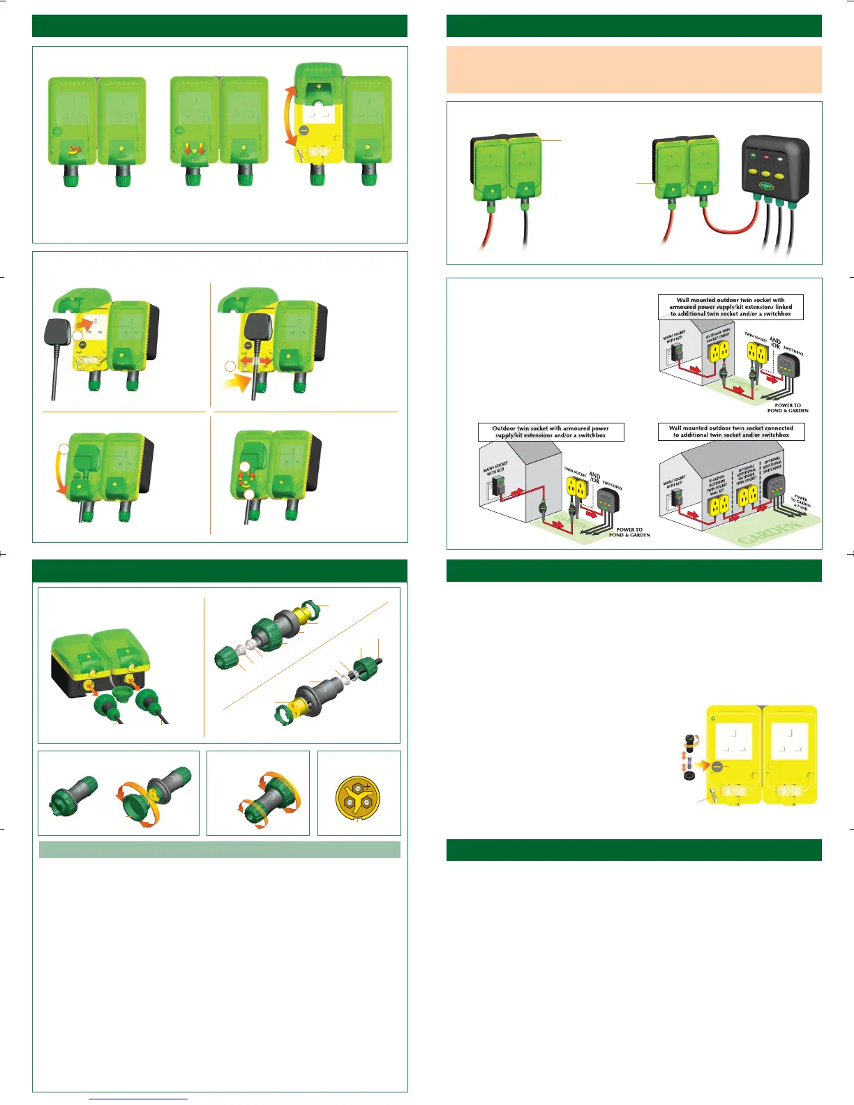
1x SOCKET OUTLET / FLEXIBLE LINKING SYSTEM OPTION
FLEXIBLE POWER LINK OPTIONS
The Powersafe twin socket has an additional third plug
and socket outlet. This power outlet can be used to
power any appliance in the garden with the same
maximum 2.2kw load as the two three pin sockets.
The Plug and socket outlet connecter can also be used
to link the mains power to a additional Twin socket, or
Powersafe switchbox. A 30cm pre prepared link cable for
this purpose has been supplied. Please follow the mains
power input instructions on the additional product fully.
IMPORTANT: Please note that the three combined line
outs must not exceed a total of 2200w when used together.
PLUG & SOCKET
OUTLET WITH
POWER LINK TO
SWITCHBOX
PLUG & SOCKET
MAINS OUTLET
MAINS IN
ADDITIONAL
MAINS OUTLET
MAINS IN
30CM LINK
CABLE
SWITCHBOX
MULTIPLE OUTLETS
POP OUT
FUSE LOCATION
FUSE
HOLDER
FUSE
FUSE
HOLDER
1.
Insert
the plug
fully into
the socket
IMPORTANT: If a number of Powersafe twin socket boxes and switchboxes are linked together the
combined maximum load for all line outs must not exceed the maximum 2200w. If the total load
exceeds 2200w the fuse in the first twin outdoor socket will blow, if this happens turn off/remove
excess load before replacing the fuse in the first outdoor twin socket.
SPARE
10AMP FUSE
Before returning your Powersafe Twin Socket to your dealer or contacting our Consumer Advice
Department, please carry out the following steps. This will solve most problems quickly and easily.
1. Ensure electrical procedures have been followed fully. Check fuses and any cable connectors.
Check mains fuse and mains RCD.
2. Return socket box to the point of purchase for inspection and advice (you will need proof of purchase).
CONSUMER ADVICE CONTACT DETAILS
Interpet (Blagdon) Consumer Advice Department, Vincent Lane, Dorking, Surrey RH4 3YX
Telephone: 0845 226 7437 (Monday to Friday 10am to 4pm except Bank Holidays - Times may vary)
Fax: 01306 876712 E-mail: customercare@interpet.co.uk
GUARANTEE
This product is guaranteed against defects in material and workmanship for 2 years from the date of
purchase, under normal usage. The guarantee DOES NOT APPLY in case of improper use, negligence,
lack of maintenance or accidental damage to the Twin Socket. If the Twin Socket fails due to a
manufacturing fault within this period it will be either repaired or replaced free of charge.
Liability is limited to replacement of the faulty product only; no other costs will be reimbursed.
This guarantee is not transferable and does not affect your statutory rights. This guarantee does not confer
any rights other than those expressly set out above. Excludes fuses and seals, which may require replacing
annually. If any parts need replacing, spares are available from your retailer.
PLUG & SOCKET WIRING
SOCKET CAP / LOCKING RING TOOL
Insert Locking
Ring Tool
Locating Slot
PLUG AND SOCKET
WIRING TERMINALS
Twist to
lock/unlock
CONNECTION &
DISCONNECTION
MAINS POWER IN SOCKET
POWER OUT / LINK
OUTLET PLUG
Gland Nut
Gland Cage
Gland
Plug Locking
Cap
Plug Housing
Plug Insert
Insert Locking Ring
Socket Insert
Socket Housing
Gland
Cable
Gland Nut
Gland Cage
B. PLUG OUTLETS
WIRING
DIAGRAM
A. SOCKET INPUT
WIRING DIAGRAM
A. MAINS POWER IN
B. MAINS POWER OUT
LINK OUTLET
E
L
N
Always wire the socket to the mains supply. Always wire the plug to the appliance to be fitted.
1. Remove the green cable gland and thread it over the prepared cable.
2. Remove the Gland cage and thread it over the cable curved face first.
3. Remove the green gland and thread this over the cable curved face first.
Important: Use the smallest suitable gland size provided to suit the cable being fitted.
The cable gland should be fitted with the cone end facing into the socket housing.
4. Remove the green threaded insert locking ring with the insert locking ring tool/socket cap provided
and place to one side in a safe place.
5. The yellow socket or plug insert is now free to be removed.
6. Thread the prepared cable which has the Gland/Gland cage/Gland nut already threaded onto it
through the grey socket or plug housing fully to allow easy wiring of the socket or plug insert.
7. The insert should be wired according to the following: (See Fig.A over page)
Yellow/green (E) symbol earth cable inserted into (E) symbol cable block and secure firmly with
cable block screw
Blue (N) Neutral cable inserted into (N) cable block and secure firmly with cable block screw
Brown (L) Live cable inserted into (L) cable block and secure firmly with cable block screw
8. Insert the yellow socket or plug insert into the grey socket or plug housing fully insuring that the plug
or socket is aligned and seated into position. (Note: use locating slot provided for correct location)
9. Replace the green insert locking ring fully using the cap tool provided.
10. Push the gland along the cable fully into the socket or plug housing.
11. Push the gland cage along the cable fully onto the gland.
12. Thread the green gland nut fully onto the grey socket housing insuring that it is firmly screwed together.
Repeat the procedure on both plug and socket. Your Plug or socket is now ready for use.
Twin_Socket_Instructions_AW 11/5/09 10:44 Page 2

 Loading...