After installation, the Detector will be activated under the
following conditions:
1. When the door is opened and magnet moves away from the
main body, the Reed Switch within the Detector will be
activated.
2. When the Normal Close (N.C.) device connected to Wire Input
Terminal 1 is activated (opened).
3. When the pull cord of the roller shutter connected to Wire
Input Terminal 2 is pulled down or retracted for set distance.
Please refer to Jumper Switch Setting section below for
setting roller shutter cord activation distance.
The Tamper Switch will be compressed against the mounting
surface when the Detector is properly installed. The tamper
switch will be activated when the Detector is removed from the
mounting location, or when its cover is removed. When the
tamper switch is triggered, the Detector will send a signal to the
Control Panel to notify the situation.
The Detector uses one 3.6V 1/2AA lithium battery as its power
source. It also features low battery detection function to notify the
Control Panel when battery voltage is low.
When the Detector is on low battery, follow the procedure below
to change the batteries.
1. Remove the Detector from mounting location, open the cover.
2. Remove the old battery.
3. Press the learn button several times to fully discharge.
4. Insert the new batteries observing correct polarity.
5. Replace the cover and re-install the Detector at mounting
location.
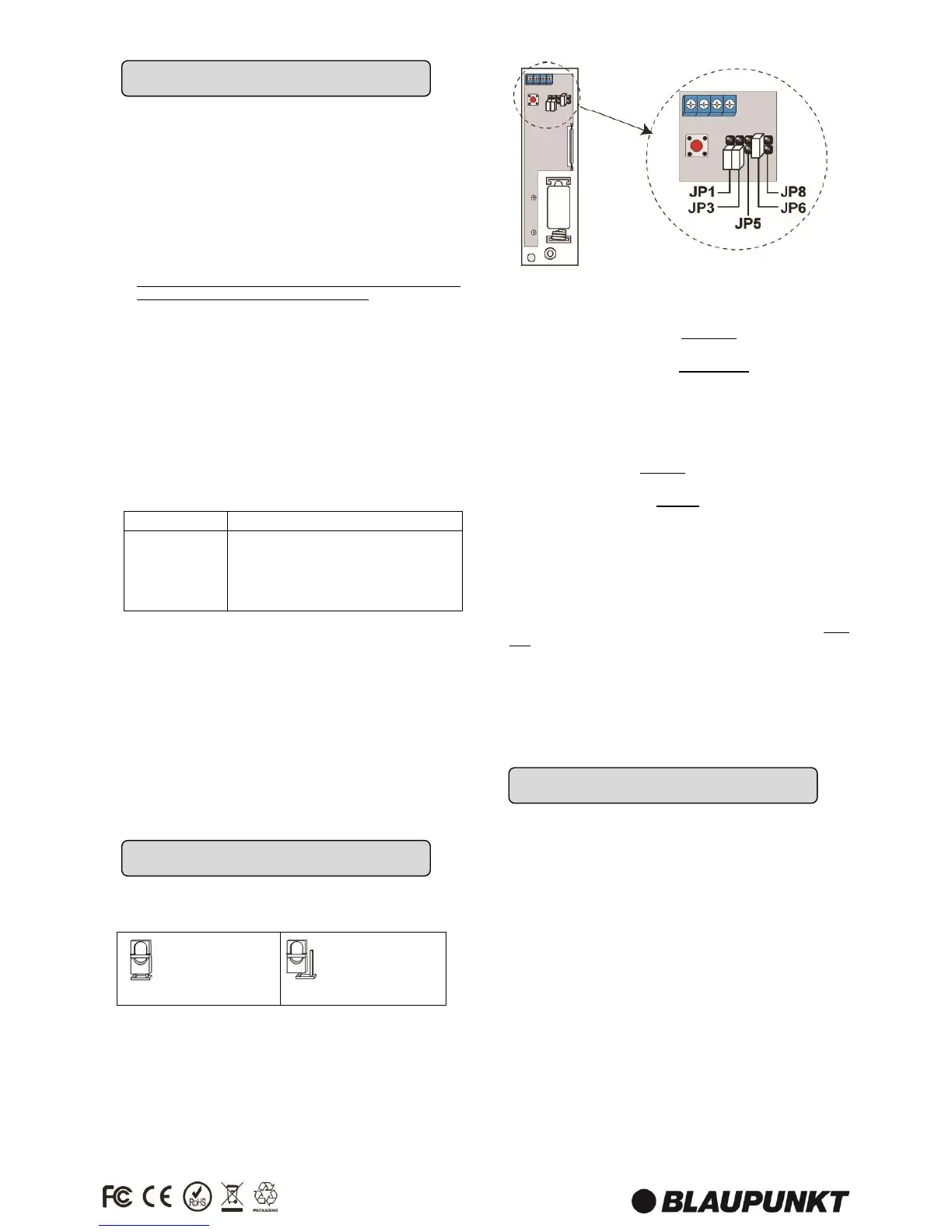
The jumper switches provides setting option for Door Contact
functions. Each jumper switch has 2 pins; the jumper setting is
determined by how the jumper is installed on the pins.
The Door Contact has 5 jumper switches, marked JP1, JP3, JP5,
JP6, JP8 on the PCB board from left to right.
JP1 – Test Mode
This jumper is used to put the Door Contact into permanent Test
Mode.
ON: The Door Contact is set to Test Mode permanently. You do
not need to press the Learn/Test button to enter Test Mode
OFF: The Door Contact is set to Normal Mode. You can still press
the Learn/Test button to enter Test Mode temporarily for 3
minutes. (Factory Default)
JP3 – Reed Switch
This jumper is used to enable or disabled the Door Contact’s
Reed Switch.
ON: The Reed Switch is Disabled. The Door Contact can only be
activated by the Wire Input Terminals
OFF: The Reed Switch is Enabled. The Door Contact can be
activated by both Reed Switch and Wire Input Terminals.
(Factory Default)
JP5, JP6, JP8 – Roller Shutter Pull Cord
Activation Distance
This jumper is used to set the distance the pull cord on the roller
shutter needs to travel before the Door Contact is activated. The
distance is measured by the number of pulse signal sent to Wire
Input Terminal 2 when the pull cord is pulled or retracted. Only
one of the 3 jumpers can be turned on at a time.
JP5 ON: The Door Contact will be activated after detecting 5
pulses from roller shutter within 10 seconds.
JP6 ON: The Door Contact will be activated after detecting 6
pulses from roller shutter within 10 seconds. (Factory Default)
JP8 ON: The Door Contact will be activated after detecting 8
pulses from roller shutter within 10 seconds.
 Loading...