336
1
2
3
4
5
6
7
8
1
2
3
4
5
6
7
8
C
B
A
14
7
10 13
16
19
3
6
9
12
15
18
2
58
11
14 17
20
C-1 C-2 C-3
RC 08
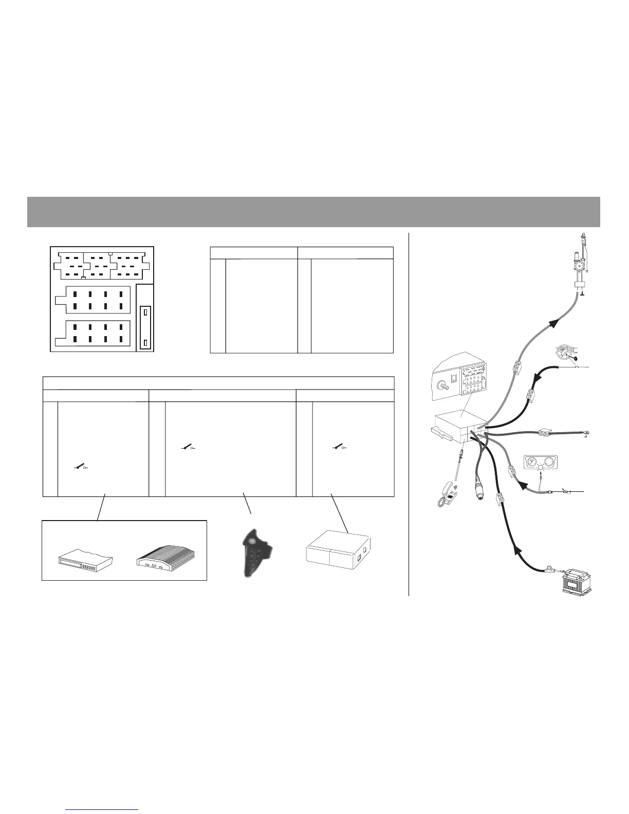
Fig.10
AB
1 — 1 Speaker out RR+
2 Telefon Mute 2 Speaker out RR-
3 Sub Out 3 Speaker out RF+
4 Permanent +12V 4 Speaker out RF-
5 Aut. antenna 5 Speaker out LF+
6 Illumination 6 Speaker out LF-
7 Kl.15/Ignition 7 Speaker out LR+
8 Ground 8 Speaker out LR-
C
C1 C2 C3
1 Line Out LR 7 - 13 Bus - In
2 Line Out RR 8 - 14 Bus - Out
3 Line Out Masse / Ground 9 - 15 -
4 Line Out LF 10 FB + 12V / RC +12V 16 12V
5 Line Out RF 11 Fernbedienung / Remote Control 17 Bus - Masse / GND
6 +12V Amplifier 12 FB - Masse / RC - GND 18 AF - Masse / GND
19 Line In - L
20 Line In - R
rt
br
or
ge/gn
rt
Relais
10A
12V
Kl.15 +12V
12V
Telefon Mute (low)
Sub - Out
CD-Changer
br braun, brown, marron, marrone, bruin,
brun, marrón, castanho
rt rot, red, rouge, rosso, rood, röd, rojo,
vermelho
ge/gn gelb/grün, yellow/green, jaune/vert,
giallo/verde, geel/groen, gul/grön,
amarillo/verde, amarelo/verde
or orange, orange, orange, arancio, oranje,
orangefärgad, naranja, cor de laranja
Einbau- und Anschlußanleitung • Installation and connection instructions • Notice de montage et de branchement •
Istruzioni di montaggio e di allacciamento • Handleiding voor inbouw en aansluiting • Monterings- och inkopplingsanvisningar •
Instrucciones para la instalación y conexión • Instrução de montagem e de conexão
Equalizer Amplifier
 Loading...