- 6 -
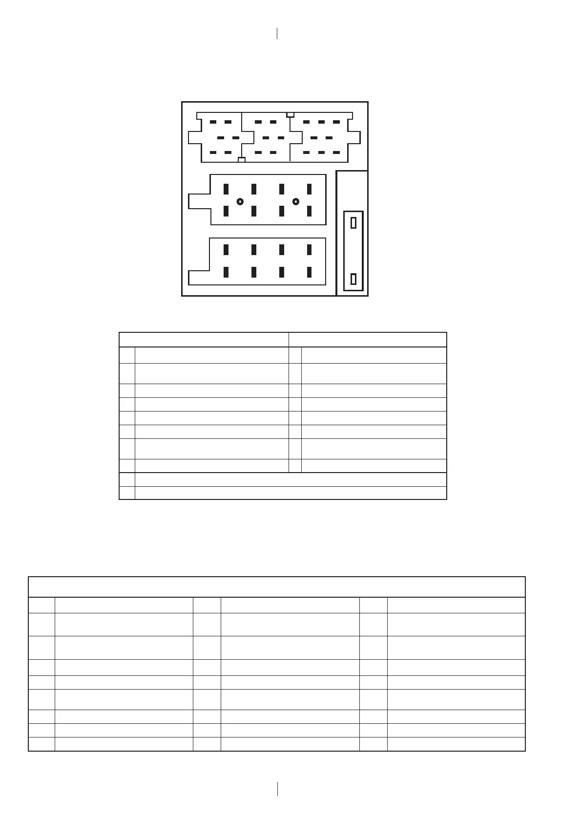
(D) Belegung des Anschlußkästchens
(GB) Pin assignment of quickfit connector
1
2
3
4
5
6
7
8
1
2
3
4
5
6
7
8
C
B
A
14
7
10 13
16
19
3
6
9
12
15
18
2
58
11
14 17
20
C-1 C-2 C-3
a
b
AB
1NC1Speaker Out (RR +) 4Ω
Telephone mute 2 Speaker Out (RR -) 4Ω
2 <2volts = active; open = not active
3NC3Speaker Out (RF +) 4Ω
4 Permanent plus (KL 30); 10 A 4 Speaker Out (RF-) 4Ω
5 Automatic antenna 5 Speaker Out (LF +) 4Ω
6 Illumination, active high (3 - 12 volts) 6 Speaker Out (LF-) 4Ω
Ignition plus, (KL 15) Speaker Out (LR +) 4Ω
7 <2.5volts = Ign.off; >7volts = Ign.on 7
8 Ground 8 Speaker Out (LR-) 4Ω
a MAUS-BUS-OUT (TXD) <0.5volts = logic 0; >3.5volts = logic 1
b MAUS-BUS-IN (RXD) <1volt = logic 0; >3.5volts = logic 1
IG für A/Pin5; C1/Pin6; C2/Pin10 + C3/P = 300 mA. IG for A/Pin5; C1/Pin6; C2/Pin10 + C3/P = 300 mA.
C
C1 C2 C3
1 Line out, 3V/10kΩ (LR) (*)7 Tel.-/Navi. AF In 10V/560Ω 13 CD-Changer ASCI IN / (+)TMC-Out
<1volt = logic 0; >3.5volts = logic 1
2 Line out, 3V/10kΩ (RR) (*)8 Tel.-/Navi. AF In 10V/560Ω 14 CD-Changer ASCI OUT / (+)TMC-Out
<0.5volt = logic 0; >3.5volts = logic 1
3 Line out ground 9 NC 15 CDC permanent plus (bloc A / pin 4)
4 Line out out, 3V/10kΩ (LF) 10 +12 V switched 16 +12 V switched
5 Line out out, 3V/10kΩ (RF) Remote control PWM 17 CD-Changer I
2
C-Bus Masse / Gnd.
11 <1volt = logic 0; >3.5volts = logic 1
6 +12 V switched 12 Remote control Ground 18 Aux Ground
19 Aux input 2V/6kΩ (L)
20 Aux input 2V/6kΩ (R)
(+) Nur Funline 4 Geräte / (+) only Funline 4 units
(*) Nur Funline 4 Geräte und Santa Cruz / (*) only Funline 4 units and Santa Cruz
 Loading...