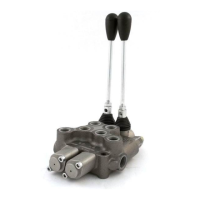
The BM40 series comprises monoblock directional control valves designed for hydraulic systems, offering precise control over actuator speed and various customizable options. These valves are suitable for a range of applications requiring reliable and efficient hydraulic control.
Function Description
The BM40 valves are monoblock directional control valves that regulate the flow and direction of hydraulic fluid to actuators. They are designed for both open and closed center hydraulic systems, with an easy conversion process between the two. The valves feature a power beyond capability, allowing for the easy addition of downstream valves. The adjustable relief valve, a standard component, ensures system protection by setting a maximum pressure. Spool control options, including spring-centered and detent, provide flexibility in operation.
Important Technical Specifications
- Work Flow / Max Flow: 35 l/min / 45 l/min
- Relief Valve Setting: 140 bar (standard factory setting)
- Relief Valve Range: 100 to 250 bar
- Inlet/Outlet Ports: 1/2" G Side / 3/8" G Top
- Work Ports: 3/8" G
- Fixing Screws: M8 (Torque: 23 Nm)
- Connectors: 3/8" G; 3/4"-16 UNF (Torque: 32 Nm)
- Plugs: 1/2" G; 7/8"-14 UNF (Torque: 45 Nm)
- Relief Valve, RVP: M20 x 1.5 (Torque: 45 Nm)
The pressure drop characteristics are detailed in the provided graphs, showing the relationship between pressure (bar) and flow (l/min) for P-T, P-A-B, and A-B-T configurations, with different spool positions (1 to 8).
Usage Features
- Corrosion Protection: Zinc plating protects against corrosion and rust, extending the lifespan of the valve.
- Precise Flow Metering: Enables accurate control of actuator speed, crucial for applications requiring fine adjustments.
- Power Beyond Capability: Allows for the seamless integration of additional valves downstream, enhancing system versatility.
- Open to Closed Center Conversion: The design facilitates easy conversion between open and closed center hydraulic systems, adapting to different system requirements.
- Customizable: Offers a variety of spool and positioner options to meet specific operational needs.
- Installation: Valves should be installed in shock and vibration-free areas, secured with M8 screws. Thread-lock accessories are recommended. The mounting position is flexible, provided the valve rests on a rigid and flat surface to prevent deformation during tightening. Hoses and fittings must be suitable for the indicated max flow and pressure. Conic fittings and reversed connections between inlet/outlet and tank lines are prohibited. Protective plugs should be removed just before connecting hoses to prevent contamination. Fittings must be tightened to the specified torque.
- Initial System Start-up: Before starting, flux oil from an auxiliary system. Operate actuators individually and without load, slowly filling the system with oil. Set the relief valve and perform a complete system test. Pressure gauge installation on the inlet section is necessary for valve calibration.
Maintenance Features
- Changing the Valve Spool and Seals:
- Remove the Handle (Part 3).
- Remove the Screws (Part 6.2) and Spool Control Cap (Part 6) using a 5 mm hex key.
- Remove the Spool Control Kit (Part 6.1) using a 5 mm hex key.
- Remove the Screws (Part 4.1) and Handle Cap (Part 4) using a 5 mm hex key.
- To remove O-ring Seals (Part 5.1), move the Spool (Part 5) just enough to expose the seals without pushing it too far past the groove, which could cut the O-ring. Remove the O-ring Seal with a pick.
- Remove the Spool through the Spool Control Cap end and remove the Handle Cap side O-ring Seal.
- Lightly oil the new Spool with clean hydraulic fluid and insert it into the valve, pushing and pulling to ensure smooth movement.
- Push the Spool back to the Handle Cap end to install the O-ring Seal in the groove.
- Slowly push the Spool from the Spool Control Cap end to expose and install the O-ring Seal in its groove.
- Install the Handle Cap and tighten screws to 8.5 Nm.
- Install the Spool Control onto the spool and tighten to 16 Nm, then install the Spool Control Cap and tighten screws to 8.5 Nm.
- Add the Handle and move it to check for sticking. If sticking occurs, loosen the Caps, realign, and re-tighten.
- Changing the Spool Control from Spring Centered to Detent:
- Remove the Screws (Part 6.2) and Spool Control Cap (Part 6) using a 5 mm hex key.
- Remove the old Spool Control (Part 6.1) using a 5 mm hex key.
- Install the new Spool Control onto the Spool and tighten to 16 Nm.
- Install the Spool Control Cap and tighten the Screws to 8.5 Nm.
- Setting the Relief Valve:
- Release the Nut (Part 1.2).
- Turn the Adjusting Screw (Part 1.1) with a 4 mm hex key wrench. Clockwise increases pressure, counter-clockwise decreases pressure.
- A pressure gauge must be installed in the inlet line when adjusting.
- Do not back out the Adjusting Screw to the point it falls out.
- Installation of Carry Over (CO) (Power Beyond Adapter): Screw the Power Beyond Adapter into the T2 port with a 27 mm hex wrench and tighten to 45 Nm. A hose must be attached to the T port and run back to the tank; failure to do so will prevent the valve from functioning correctly.
- Installation of Closed Center Plug (CCP): Screw the Closed Center Plug into the T2 port with a 10 mm hex key and tighten to 45 Nm. A hose must be attached to the T port and run back to the tank; failure to do so will prevent the valve from functioning correctly.
- Installation of Relief Valve Plug (RVP): Remove the Relief Valve (Part 1) with a 22 mm wrench. Take out the Check Valve (Part 2) and install it on the Relief Valve Plug. Screw the Relief Valve Plug into the Relief Valve port with an 8 mm hex key and tighten to 45 Nm.
Safety Warnings:
- All hydraulic valves must be properly installed to prevent personal injury or property damage.
- Ensure all pressure is relieved in hydraulic lines before installation or servicing.
- Escaping hydraulic fluid under pressure can penetrate skin; do not use hands to check for leaks.
- Remove all weight from cylinders or motors before disconnecting hydraulic lines.
- Disconnecting hydraulic lines under load can cause unexpected rapid machine movement.
- Do not exceed operating specifications for pressure, flow, or temperature.
- Always use a pressure gauge when adjusting a relief valve to prevent overpressure and potential component failure.