DC Installation (continued)
3. Install battery bank voltage monitor wires
The panel is supplied with a VSM PN 1850 to monitor the
voltage of three separate sources, usually the batteries. Connect a
minimum 16 AWG red wire from each source to be monitored as shown
in the VSM PN 1850 instructions. There should be a 5A fuse in each
positive wire near each source.
4. Install branch circuit wires
Determine the proper wire size for each branch circuit using the
guidelines in step 4. Verify that the standard 15 amp circuit breakers
installed in the panel are large enough for each branch circuit. Remove
and replace with a higher amperage any that are undersized. Connect
the positive (red) branch circuit wires to the load terminals of each circuit
breaker. Connect each negative (black) branch circuit wire to the DC
Negative Bus. DO NOT CONFUSE THE DC NEGATIVE BUS WITH THE
DC GROUNDING BUS.
5. Optional—install grounding system wire
The grounding wire (bare, green or green with yellow stripe and normally
non-current carrying) should not be confused with the negative ground
wire (black or yellow and normally current carrying).
In Boatowner’s Illustrated Electrical Handbook,CharlieWingidenties
three purposes of DC Grounding:
1. Holding conductive housings of low voltage (under 50 volts) DC
devices at ground potential by providing a low resistance return
path for currents accidentally contacting the device cases.
2. Providing a low resistance return path for electrical current,
preventing stray currents that may cause corrosion.
3. Grounding metal electrical cases to prevent emission from inside
or absorption from outside of radio frequency noise (RFI).
ABYC requires that grounding wires be sized no smaller than one wire
size under that required for current carrying conductors supplying the
device to which the grounding wire is connected.
6. Installation of Backlight System
Connect the yellow negative wire to the panel negative bus. Do not
confuse with the AC neutral bus.
To activate the label lights by the boat’s battery switch, connect the red
positive wire to the DC positive bus. Do not confuse with the AC
hot bus.
To activate the label lights by an independent switch or breaker,
connect the red positive wire to the load side of a DC switch or breaker.
7. Optional Branch LEDs
This panel is supplied with LEDs pre-installed in all optional branch
positions. For future expansion of the panel remove the positive leg of
the LED from the negative bus and connect it to the load side of the
corresponding branch circuit breaker.
Note
This Blue Sea Systems electrical distribution panel is furnished with 15A
circuit breakers for DC branch circuits. These ratings will satisfy the vast
majority of marine circit protection situations. As shown in the Wire Sizing
Chart, even 16 AWG wire, which is the minimum wire size recommended by
ABYC, has an allowable amperage greater than 20A.
AC Installation
1. Install branch circuit wires
Determine the proper wire size for each branch circuit using the chart
below. Verify that the standard circuit breakers installed in the panel are
correct for each branch circuit. Remove and replace any that are
incorrectly sized. The circuit breaker must have a rating less than the
allowable amperage of the wire, yet greater than the circuit’s
continuous current.
Connect each branch circuit hot (black) to the appropriate load terminal.
Connect each branch circuit neutral (white) to one of the screws on the
neutral bus. Connect each branch safety ground wire (green) to one of
the screws of the safety ground bus.
Do not confuse the neutral current carrying wires (sometimes called
ground) with the green normally non-current carrying wires (sometimes
called grounding). These two wires must be connected only at the source
of power, nowhere else.
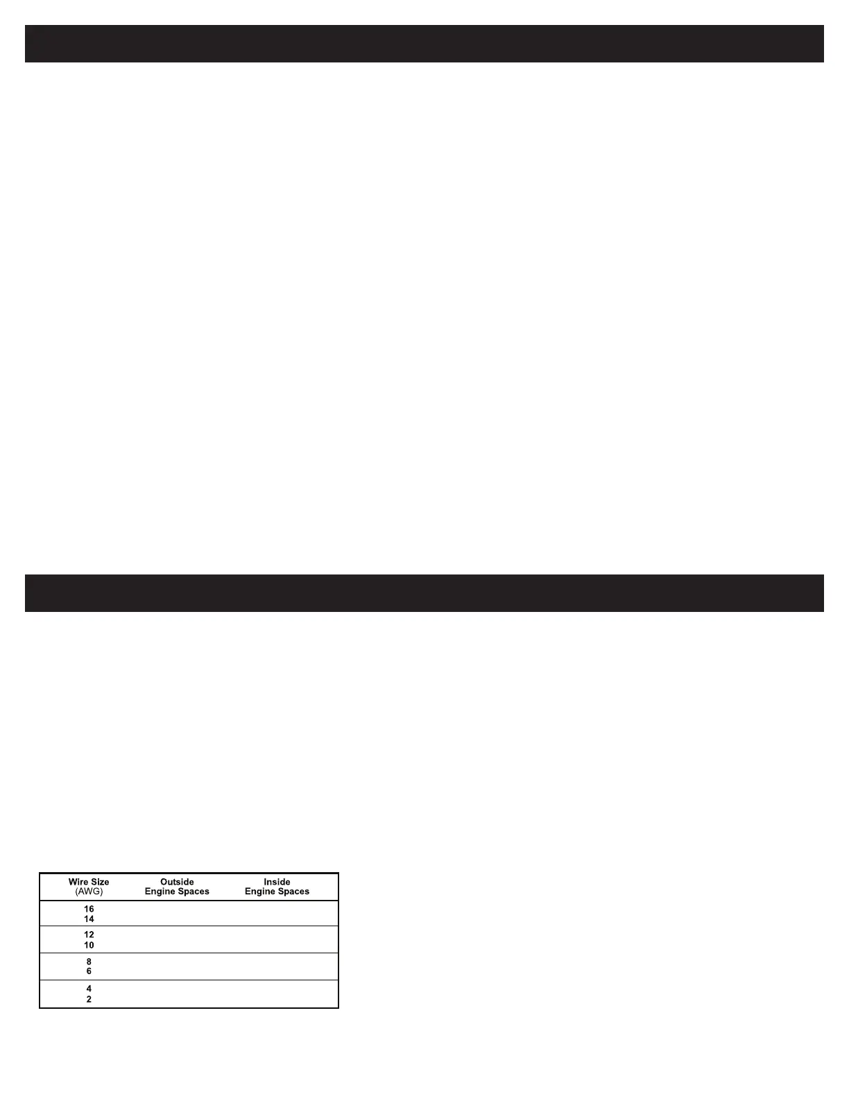
Wire sizing chart
Use the wire sizing chart below to determine the proper wire sizes.
2. Install feed circuit wires
Install the feed wires from the shore power inlet or other AC source,
referring to the wire sizing chart to select the correct wire size. Connect
the black AC hot, white AC neutral and green AC safety ground as shown
in the illustration.
If the feed wires are from the shore power inlet or the electrical
attachment point of a permanently installed shore power cord and the
inlet or attachment point is more than 10 feet from this panel, an
additional fuses or circuit breakers must be installed within 10 feet of the
shore power inlet. The measurement is made along the conductors.
3. Optional Branch LEDs
This Panel is supplied with LEDs pre-installed in all optional branch
positions. For future expansion of the panel remove the hot leg of the
LED from the AC Neutral Bus and connect it to the Load side of the
branch circuit breaker.
Note
This Blue Sea Systems electrical distribution panel is furnished with 15A or
8A circuit breakers for AC branch circuits. 15A circuit breakers are used in
all 120V panels and 8A circuit breakers are used in all 230V panels. These
ratings will satisfy the vast majority of marine circuit protection situations.
ABYC E-11 Table VI-B 105˚ C ( 221˚ F) Wire
Note
: This chart assumes wire with 105° C (221° F) insulation
rating and no more than 3 conductors are bundled.
Not suitable for sizing flexible shore power cords.
Blue Sea Systems recommends that the feeder wires from the
power inlet to the panel should be 10
AWG for 30A systems and
AWG for 50A systems.
17.5
24.5
31.5
42.0
56
84
112
126
11.9
20.8
26.8
35.7
47.6
71.4
95.2
107.1
980037800 Rev. 001
Page 2 of 4
 Loading...