"inlet" side. If installed horizontally, ensure that the wire- side faces upwards. From
end to end, the Cell with both Unions is approximately 15 ¾" in length; the typical
gap required is 13 ¼".
Refer to the overview diagram on page 4 for alternate configurations. For combined pool
and spa systems with a spillover, allow chlorination for both the pool and spa during
spillover but preventing possible over-chlorination when operating the spa only. Vertical
Installation Kits are also available to minimize plumbing space required and increase
ease of installation.
TIP: Double-check that all Cell and Flow Switch cables can reach the Control Panel.
Note: For installations with 1 ½" plumbing, use 2" to 1 ½" reducer bushings with flow
switch, and use alternate 1 ½" Cell Unions; be sure to note any new or additional
measurements before cutting pipe.
After determining the section of plumbing to install the Flow Switch and Cell, measure out
and mark the selected area.
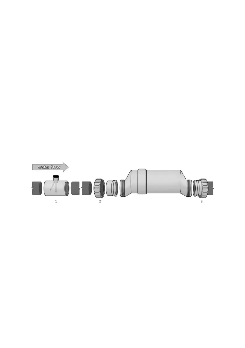
1. To install the Flow Switch, cut out a section of pipe at the desired installation
location. Use PVC Primer to clean and prepare the pipe ends and interior of Flow
Switch. Using plumbing Solvent Cement, glue the Flow Switch to the pipe ends.
Ensure excess glue does not become affixed to movable parts within Flow Switch.
IMPORTANT: To insure proper operation, verify that the arrow on the flow switch
(located on the black plastic) points in the direction of water flow; the water flow
must depress the hinged activator inside of the Flow Switch. This portion is
threaded and may be turned during service; additional thread seal tape may be
added if necessary.