Specifications 105
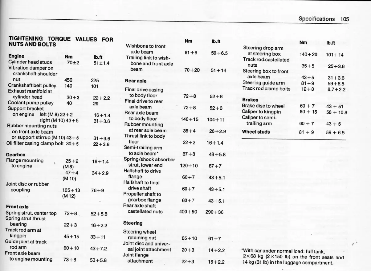
TIGHTENING TORQUE VALUES FOFt
NUTS AND BOLTS
Engi rie Nm lb.ft
Cylinder head studs 70±2 51 ±1.4
Vìbration damper on
crankshaft shoulder
nut 450
Crankshaftbeltpulley 140
Exhaust manifold at
cylinder head 30+3
Coolant pump pulley 40
Support bracket
onengine left(M8)22+2
right (M 10) 43+5
Rubber moLinting nuts
on front axle beam
or support stirrup (M 10) 43+5
0il filtercasing clamp bolt 30+5
Gearbox
Flangemounting . 25+2
to engine (M 8)
47+4
(M I O)
Joint disc or rubber
cOupling
105+13
(M 12)
Front axle
Springstrut,centertop 72+8 `
Spring strut thrust
bearing
Track rod arm at
kingpin
Guidejoint at track
rod arm
Front axle beam
to engine mountjng
22+3
45+15
60 + 1 0
73+8
325
101
22+2.2
29
16+1.4
31 + 3.6
31 +3.6
22+3.6
18+1.4
84+2.9
76+9
52+5.8
16+2.2
33 + 1 1
43+7.2
53+5.8
Wishbone to front
gD(Ie beam
Trailing link to wjsh-
bone and front axle
beam
Rear axle
Final drive casing
to body floor
Final drive to rear
axle beam
Rear axle beam
to body f loor
FÌubbermounting
at rear axle beam
Thrust link to body
floor
Semi-traj ling arm
to axle beam .
Spring/shock absorber
strut, lower end
Halfshaft to drive
flange
Halfshaft to final
drive shaft
Propeller shaft to
gearbox flange
F`ear aD(le shaft
castellated nuts
Steering
Stering wheel
retaining nut
Joint disc and univer-
sal joint attachment
Joint flange
attachment
Nm lb.ft
81 +9 59+6.5
70+20 51 +14
72+8 52+6
72+8 52+6
140+15 104+11
36+4 26+2.9
22+2 16+1.4
67+8 48+5.8
120+10 87+7
60+7 43+5.1
60+7 43+5.1
60+7 43+5.1
400+50 290+36
85+10 61 +7
20+3 14+2.2
22+3 16+2.2
Steering drop arm
at steering box
Track rod. castel lated
nuts
Steering box to f ront
axle beam
Steering guide arm
Track rod clamp bolts
Brakes
Brake disc to wheel
Caliper to kingpin
Calipertosemi-
trailing arm
Wheel studs
Nm lb.ft
140+20 101+14
35+5 25+3.6
43+5 31 +3.6
81 +9 59+6.5
12+3 8.7+2.2
60+7 43+51
80+ 15 58+10.8
60+7 43+5
81 +9 59+6.5
•With car under normal load: full tank,
2X68 kg (2X150 lb) on the front seat§ and
14 kg (31 lb) in the luggage compartment.