Valve clearance should be 0.10-0.15 mm
(.004-.006")for Intake, and (0.10-0.20mm)
(.004-.008") for exhaust, with the engine cold.
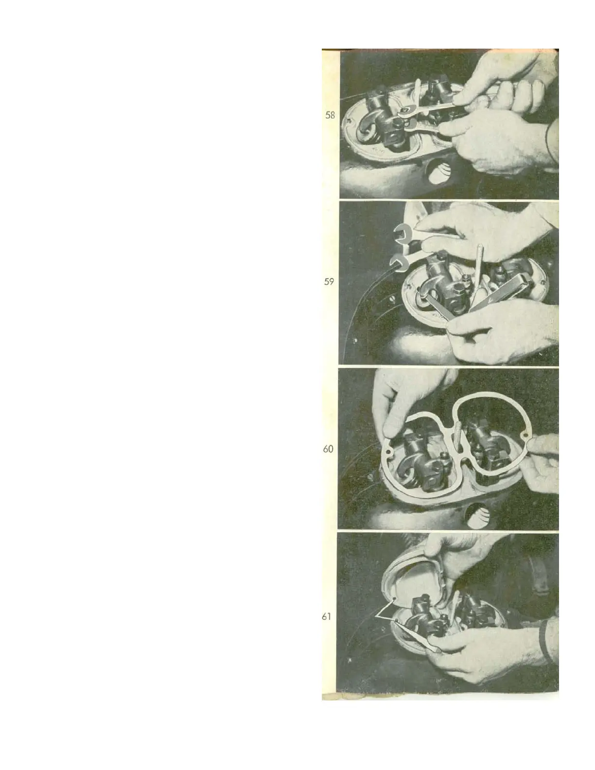
The adjustment and re-adjustment of the
valves requires two 12mm spanners. First
slacken the locknut (figure 58) then turn the
adjusting screw as required until the correct
amount of play is felt with the feeler-gauge
inserted between rocker arm and valve stem
end (figure 59). When this is obtained, hold
adjuster with its spanner and retighten the
locknut securely. When this nut is properly
tightened, check the play again, to make cer-
tain that it has not been altered while
tightening the nut.
When adjusting the valves one should inspect
the rocker box cover gasket and replace it, if
necessary, in order to ensure the proper
sealing of rocker box (figure 60). Place the
gasket in a way that the two locating pins fit in
the two holes of the gasket. Special care
should be used in replacing the rocker
covers, so that the locating pins engage
exactly in the corresponding drilled holes
provided in these units. When the locating pin
is missed, and the cover is fitted incorrectly,
the gasket does not seal properly and the
consequences are deformation of the rocker
cover and continuous oil leakage (figure 61).
The figures illustrating the servicing of the
valves in this booklet are shown with the
engine in a complete accessible condition
after removal of the body. Normally, these
jobs are performed through the cover plate
located behind the seat squab, as shown on
figure 54.
24