133 S130 Operation & Maintenance Manual
ELECTRICAL SYSTEM
Description
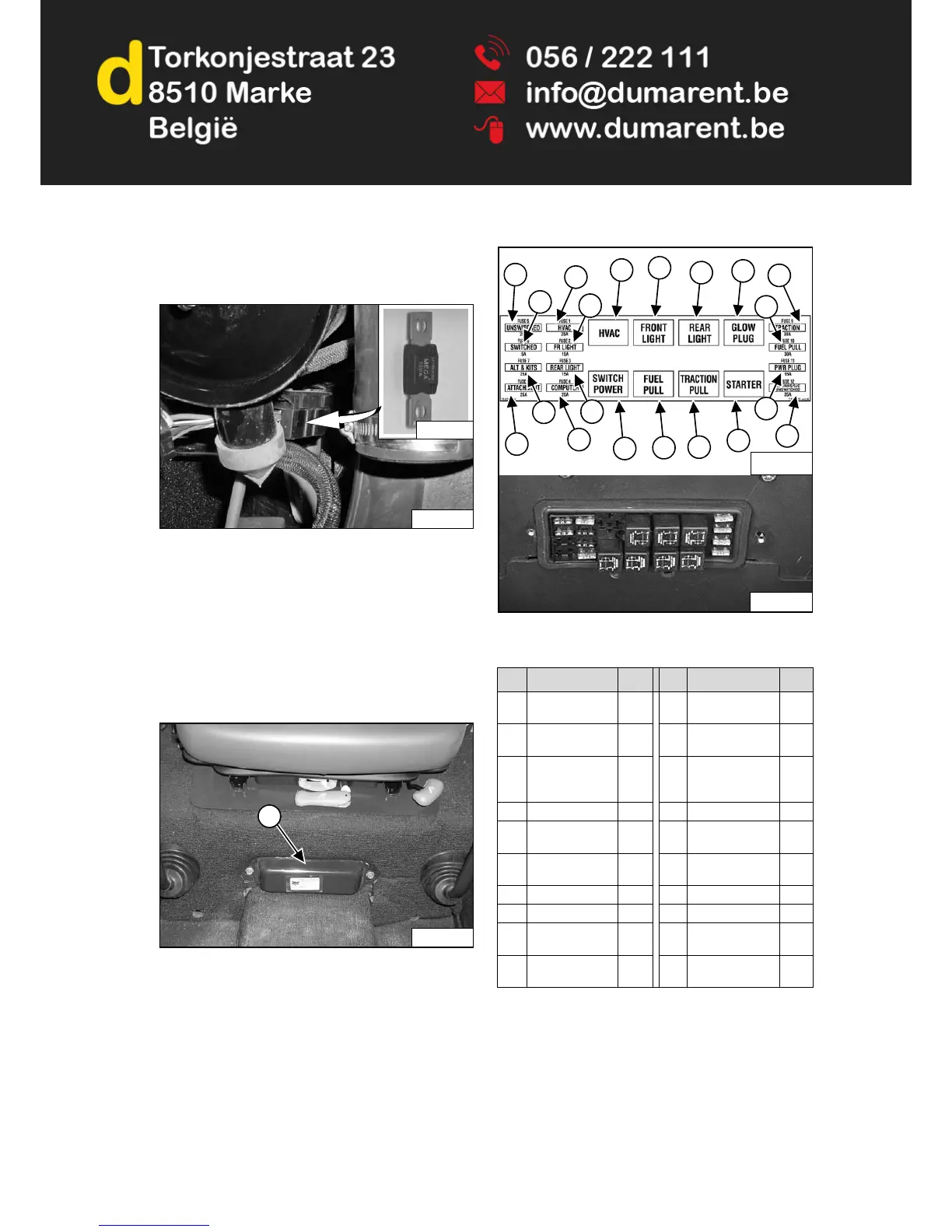
Figure 192
The loader has a 12 volt, negative ground alternator
charging system. The electrical system is protected by
fuses located in the cab on the steering control panel,
and a 100 amp master fuse [Figure 192] in the engine
compartment on the left side of the engine, under the air
cleaner. The fuses will protect the electrical system when
there is an electrical overload. The reason for the
overload must be found before starting the engine again.
Fuse And Relay Location / Identification
Figure 193
The electrical system is protected from overload by fuses
and relays under the fuse panel cover (Item 1) [Figure
193]. A decal is inside the cover to show location and
amp ratings.
Remove the cover to check or replace the fuses.
Figure 194
The location and sizes are shown below and [Figure
194].
R - Relay
REF DESCRIPTION AMP REF DESCRIPTION AMP
1 Unswitched
Horn
25 11 Front & Marker
Lights
R
2 ACS/AWS/SJC
Switched
5 12 Fuel Shutoff R
3 Alternator &
Accessories
Back-up Alarm
25 13 Rear Lights R
4 Attachments 25 14 Traction R
5 Heater & Air
Conditioning
25 15 Glow Plugs R
6 Front & Marker
Lights
15 16 Starter R
7 Rear Lights 15 17 Traction 30
8 Bobcat Controller 25 18 Fuel Shutoff 30
9 Heater & Air
Conditioning
R 19 Power Plug 15
10 Switch Power R 20 ACS/AWS/SJC
Unswitched
25
 Loading...