113 S450 Operation & Maintenance Manual
ATTACHMENTS (CONT’D)
Installing And Removing The Attachment (Power Bob-Tach) (Cont’d)
Installing (Cont’d)
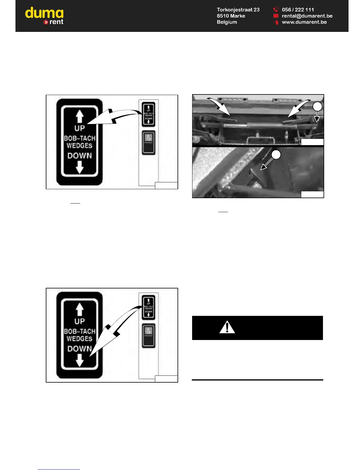
Figure 134
Push and hold
BOB-TACH WEDGES “UP” switch (Right
Switch Panel) [Figure 134] to make sure the levers are
fully raised (wedges fully raised).
NOTE: The Power Bob-Tach system uses
continuously pressurised hydraulic fluid to
keep the wedges in the engaged position and
prevent attachment disengagement. Because
the wedges can slowly lower, the operator
may need to reactivate the switch (BOB-TACH
WEDGES “UP”) to be sure both wedges are
fully raised before installing the attachment.
Figure 135
Figure 136
Push and hold
BOB-TACH WEDGES “DOWN” switch
(Right Switch Panel) [Figure 135] until levers are fully
engaged in the locked position [Figure 136] (wedges
fully extended through the attachment mounting frame
holes).
Both levers must contact the frame as shown when
locked (Item 1) [Figure 136].
If both levers do not engage in the locked position, see
your Bobcat dealer for maintenance.
The wedges (Item 2) [Figure 136] must extend through
the holes in the mounting frame of the bucket (or other
attachment), securely fastening the bucket to the
Bob-Tach.
AVOID INJURY OR DEATH
The Bob-Tach wedges must extend through the holes
in the attachment mounting frame. Levers must be
fully down and locked. Failure to secure wedges can
allow attachment to come off.
W-2715-0208
 Loading...