Do you have a question about the Bochi Machine Tool Group Co. CS6140 Series and is the answer not in the manual?
General rules for safe operation, maintenance, and repair of the machine.
Specific safety precautions for machine operation, electrical tools, and personal protective equipment.
Environmental conditions for safe and optimal machine operation, including temperature and humidity.
Precautions for handling electrical components, wiring, and power supply safely.
Explanation of danger and warning signs displayed on the machine for user safety.
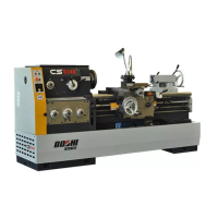
Describes the various operations and features the lathe can perform, including turning and threading.
Comprehensive table detailing technical specifications for different lathe models.
Lists metric drive parts, their specifications, materials, and heat treatments.
Lists inch drive parts with their specifications, materials, and heat treatments.
Details bearing types, specifications, quantities, and their locations on the machine diagram.
Identifies and describes the function of various controls on the machine.
Explains operational methods including drive system, feed system, carriage, and apron operations.
Checks required before applying power to ensure safe operation and correct installation.
Details machine operation, wiring diagrams, and electrical part identification.
Describes how oil is pumped and piped to lubricate headstock components.
Explains drop lubrication of parts in the feeding case using wool strings.
Details oil circulation and lubrication methods for apron components.
Outlines lubrication of carriage and other guide ways using hand pump and oil gun.
Specifies lubrication for lead screw, operating rod, and idle pulley in the gearbox.
Instructions for safely hoisting the machine using wire ropes and avoiding damage.
Steps for unpacking the machine and checking accessories against the packing list.
Procedures for correctly installing the machine on a foundation for accuracy and longevity.
Guidance on removing anti-rust agents and cleaning machine parts before use.
Steps for performing a dry run and checking machine operability before actual work.
Periodic lubrication requirements for all running and sliding parts to ensure good operation.
Points to note during machine operation, including speed changes and brake usage.
Key maintenance tasks like V-belt tension, cleaning, and lead screw care for accuracy.
Describes machine bed structure, motor/pump location, and drive belt adjustment.
Details the geared drive headstock, friction clutch adjustment, and brake band adjustment.
Covers tailstock movement, clamping, adjustment, and bed ways interface.
Explains cross slide adjustment for transmission clearance and sliding way adjustment.
Describes apron controls for carriage movement and safety clutch adjustment.
Details adjustment of anti-thrust bearings in the feeding case for thread cutting accuracy.
Instructions for changing gears for multiple threads and adjusting gear engagement.
Covers mounting and removing chucks/driving plates and spindle nose structures.
Details mounting chucks/driving plates onto CS6140 series spindle nose.
Details mounting chucks/driving plates onto CS6140B series spindle nose.
Machining diagram and specifications for the bushing wear part.
Machining diagram and specifications for the lever wear part.
Machining diagram and specifications for the friction plate wear part.
Machining diagram and specifications for the nut wear part.
Machining diagram and specifications for the screw wear part.
Lists standard, optional accessories, and necessary tools for the machine.
Explains the purpose and function of the foot brake system.
Describes the components and operational principle of the foot brake.
Refers to electrical diagrams and explains the function of limit switches and controls.
Details adjustments for pedal angle, height, and cam settings for the foot brake.
Lists and illustrates diagrams for easy-worn parts related to the foot brake.
States the attachment's purpose for taper turning and pipe threading.
Lists key specifications like max. taper length and swivel angle.
Refers to diagram for the structure of the taper turning attachment.
Instructions on adjusting the scale and setting up the attachment for taper turning.
Warnings and procedures for using, removing, and lubricating the attachment.
| Brand | Bochi Machine Tool Group Co. |
|---|---|
| Model | CS6140 Series |
| Category | Lathe |
| Language | English |