:
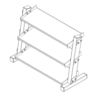
Assembly Instructions
Assembly of the GDR10 takes professional installers
about ½ hour to complete.
Professional installers are highly recommended!
If this is the rst time you have assembled this type of equipment, plan on signi cantly more time. How-
ever, if you acquire the appropriate tools, obtain assistance, and follow the assembly steps sequentially,
the process will take time, but is fairly easy.
Read all “Notes” on each page before beginning each
While you may be able to assemble the GDR10 us-
ing the illustrations only, important safety notes and
other tips are included in the text.
The basic tools that you must obtain
before assembling the GDR10 include but
• Standard / Metric Allen Key Set
• Phillips / Flathead Screwdriver
NOTE: The bottles that are marked “Poison” is
your touch up paint. Keep away from
To n d out the length of a particular bolt, measure its
shank (the long, narrow part beneath the head) using
The GDR10 has a maximum weight limit of 40lbs.
Ordering Replacement Parts
Ordering Replacement Parts
If you need to order replacement parts
please be prepared to provide the
following information when contacting us
so that we can assist you better.
4. Part # and Description
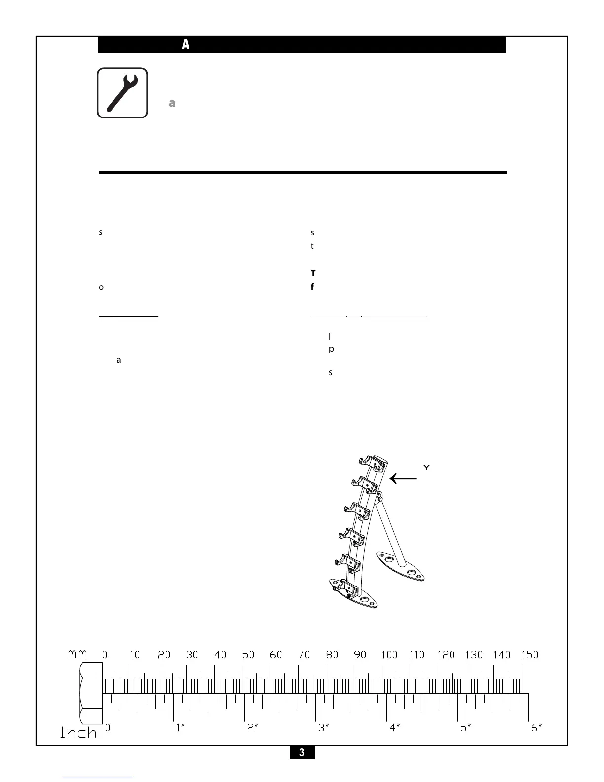
YOUR S/N # CAN
BE FOUND HERE
ON BACK.