10
S T E P
3
Be careful to assemble all components
in the sequence they are presented.
NOTE:
Finger tighten all hardware in this step unless otherwise noted.
Some components may be pre-assembled
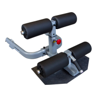
A. Insert End Cap (53) and Round End Caps (54) into Foot Brace (25).
B. Attach Grip Tapes (58) to Foot Brace (25).
C. Insert Plastic Bushings (57) into the tubing on Bottom Frame (20) as shown.
D. Slide Foot Brace (25) into Bottom Frame (20) as shown in the diagram.
E. Secure Foot Brace (25) by inserting 5/16” x 3/4” Socket Head Bolt (59) as shown.
NOTE: Do not overtighten Socket Head Bolt (59).
F. Insert Rubber Covers (42) onto the hooks on Top Frame (19).
G. Insert End Caps (16) into Top Frame (19).
H. Slide Shaft Covers (50) onto Guide Rods (27).
I. Secure Top Frame (19) as shown by using:
Two 31 (10*20mm hex head bolt)
Two 36 (10mm washer)
Two 12 (12*105mm hex head bolt)
Four 15 (12mm washer)
Two 14 (12mm nylon nut)
J. Slide Shaft Covers (50) into Top Frame (19) and turn.
Secure Shaft Covers (50) by tightening 5/16” x 5/16” Allen Screw (55).