Do you have a question about the Bongshin BS-3520 and is the answer not in the manual?
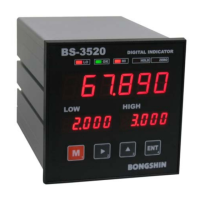
Overview of the product's features and capabilities.
Safety precautions and important warnings for product usage.
Explanation of the status lamps (LO, OK, HI, HOLD, ZERO) and their meanings.
Details on the function and operation of each key on the front panel.
Details on AC power input and frame ground terminals.
Description of the serial output port for data communication.
Detailed guide for connecting load cells, including summing box.
Description of input terminals like ZERO, HOLD, COM1.
Description of output terminals like LO, OK, HI, COM2.
Information on selecting DAC or BCD output options.
Instructions for using terminal blocks and replacing the fuse.
How to select different calibration modes (d-CAL, A-CAL, L-CAL).
Method for digital calibration without actual load.
Method for calibrating with actual load for zero and span.
Method for non-linear calibration using up to 4 points.
Method for digital zero calibration, with or without external input.
Automatic zero point update using the zero tracking function.
Automatic zero calibration when power is turned on.
Step-by-step guide to enter and navigate function settings.
Settings for polarity, decimal point, and min gradation.
Settings for display conversion speed and container value (offset).
Configuration options for the hold function (None, Edge, PK).
Selection and configuration of relay operation modes.
Settings for hysteresis width and zero tracking width.
Setting the time for zero tracking operation.
Setting for automatic zero point adjustment on power-on.
Selection of analog output modes (e.g., voltage, current).
Calibration for analog Lo/High output and minute calibration.
Fine-tuning analog output for zero and span.
Configuration for communication ID, speed, data length, and parity bit.
Settings for output count, format, and RS-422/485 interface.
How to select and configure the hold mode (None, Edge, PK).
Explanation of Edge hold and Peak hold modes.
How to operate the hold function using keys or external input.
How to select and set relay operation modes.
Setting Lo/Hi and RY1/RY2/RY3 relay values.
Explanation of comparator modes (Basic, High, Low, Low Low High).
Function to prevent output chattering using hysteresis.
How to select analog output modes (e.g., voltage, current).
Specifications and wiring for DAV/DAI analog outputs.
Procedure for calibrating analog output zero and span.
Fine-tuning analog output for zero and span.
Specifications and pinout for BCD parallel output.
Details on RS-232C, RS-422, RS-485 interfaces.
Wiring diagrams for RS-232C, RS-422, and RS-485 connections.
Examples of 1:1 and multiple connections for RS-485.
Explanation of stream and command modes for serial data.
Details on AND format and ASCII code mapping.
How to enter and use different check modes.
Checking the load cell output voltage (mV) directly from indicator.
Selecting DAC or BCD output modes.
Verifying the analog output voltage/current.
Verifying the BCD output data.
Resetting all settings to factory defaults.
Procedure to activate the key lock function.
Procedure to deactivate the key lock function.
List of error displays, their causes, and countermeasures.
Steps to inspect the load cell when it is unstable.
Methods for diagnosing load cell connection and performance.
Illustrations of display patterns for different characters.
| Brand | Bongshin |
|---|---|
| Model | BS-3520 |
| Category | Touch Panel |
| Language | English |