5
2.
e. Install the foot lever R using the M8-85
carriage bolt N, nylon washers O, lock
washer P, and nut Q.
3. Assemble the back corners, to the right are
the components you will need:
a.
Install the back wheel K using the M6-45
axle bolt V, nylon wheel bushing T, and M6
lock nut U.
4. Carefully measure the footprint of your machine (or
whatever you are mobilizing) and add about 1” to the
dimension. (1” allows clearance for the fasteners).
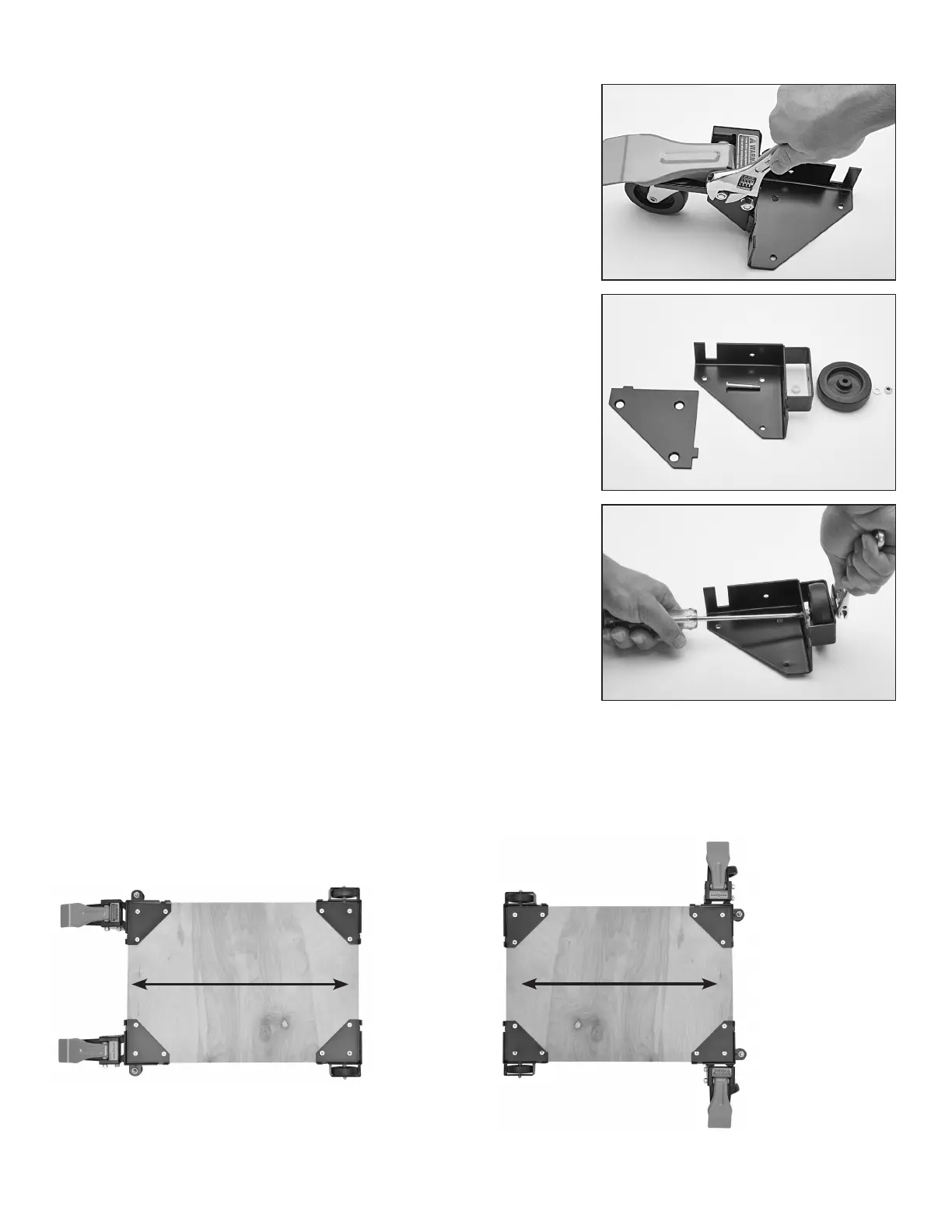
5. Review the assembly examples shown below to help
you determine the fixed wheel, caster and leveler
placement. As these are examples only, you must
determine what best suits your particular machine’s
requirements for stability.
Tighten all hardware securely
2 e.
3
3 a.
Assembly Examples
Be sure to follow Safety and Assembly Instructions. Keep in mind the actual
operation of your machine and the effect it has on overall stability.
A long, narrow
base, such as on
a jointer, would
benefit from this
arrangement. Most
machines may be
arranged to the
convenience of
the user.
A short, narrow
base, such as found
on a drill press
or bandsaw, may
benefit from this
arrangement. Due to
swivel rotation, base
may sit out of level.
Rotate swivel wheel
away from base to
correct.
Direction of Roll
Direction of Roll