PI − 34.51 enProduktinformation FMC−120−DKM / ESTGLT
Page 8 of 18
BDL−F.01U.066.178
A2.en/ 11.04.2007
ST−FIR/ PRM1 / sib
5. Device structure
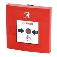
The non−automatic fire detector is available in several variants and essentially consists of the
following elements.
1
7
5
2
3
4
8
2
6
9
Pos. Designation
1 Plastic housing
2 Cable ducts (interchangeable), for cable inlet and outlet. The cable
can also be ducted through openings in the rear wall of the housing.
3 Connection terminal strip
4 Detector door with replaceable glass pane, hidden lock
(and seal, for Form H)
5 Glass pane
6 Display (LED)
7 PC board (with protective coating for Form H) The PC board is
clipped onto the floor of the housing.
8 Trigger mechanism (clipped onto the PC board), consisting of plastic
frame and push button with spring.
9 Reset lever (locking mechanism only for manual call points)
 Loading...
