Automatic Detectors LSN improved Installation | en 11
Bosch Sicherheitssysteme GmbH Operation Guide 2019.11 | 4.0 | F.01U.025.877
3 Installation
Notice!
The 520 Series Detectors may only be installed with an FAA‑500 Detector Base in
combination with an FAA‑500‑BB Ceiling Mount Back Box or an FAA‑500‑SB-H Surface Mount
Back Box.
Notice!
By default, the bases are equipped with a spring for mounting the detector in concrete and
wooden ceilings. This spring is identifiable by the blue marking. For mounting a detector in a
false ceiling panel you can use the additional, softer spring in the package (yellow marking).
In this use case, the detector must not be subjected to strong vibrations (> 350 m/s). The
shock resistance according to EN 54-7 is not warranted then.
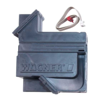
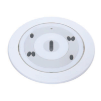
3.1 Ceiling Mount Back Box
Figure3.1: Ceiling mount back box
The ceiling mount back box (refer to figure) is made of white polypropylene.
It has four cable bushings with tightly-closing rubbers lips of polyflam that are suitable for
cable diameters up to 1.4cm.
When used with a base, approx. 30cm of cable length can be accommodated in the upper
area of the ceiling mount back box.
Notice!
The false ceiling may have a maximum thickness of 32mm.
Above the false ceiling, a free height of at least 11cm is required.
4 Bore a circular hole with a diameter of 130mm (tolerance -1mm to +5mm) in the false
ceiling.
Notice!
A hole saw with Ø 133mm can be obtained from:
Wittmann-Komet, Metal Cutting Saws GmbH & Co. KG, Alte Str. 28, D-79576 Weil am Rhein,
Tel.++49‑7621‑9783-0, www.wittmann-komet.de
Figure3.2: Plan view and side view of the ceiling mount back box FAA‑500‑BB
 Loading...