Automatic Detectors LSN improved Installation | en 13
Bosch Sicherheitssysteme GmbH Operation Guide 2019.11 | 4.0 | F.01U.025.877
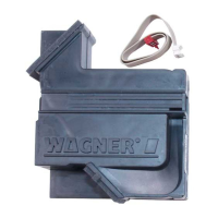
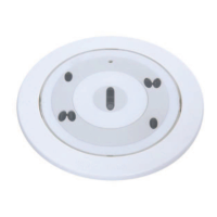
Connecting the base
Wire up the LSN base according to the labeling in the outer ring (3).
Figure3.5: Plan view base
Position Description Position Description
1 Connection terminals 3 Labeling on LSN connections
2 Mount for cable ties 4 Fastening slot
MPA
+V
0V
LSN a1/a2
LSN b1
wh wh
gn
rd rd
bk
ye
ye
b2
FAA-500(- R)
gn
bk
3
2
1
Figure3.6: Connection of bases
Position Description Position Description
1 Fire panel 3 Next detector
2 Remote indicator (optional), not
for relay bases
 Loading...