Automatic Detectors LSN improved Installation | en 15
Bosch Sicherheitssysteme GmbH Operation Guide 2019.11 | 4.0 | F.01U.025.877
3.3 Address Allocation
The detector's address is allocated by setting three rotary switches located on the back of the
device.
Use a flat-bladed screwdriver to position each switch. The switches will click when turned.
All detectors delivered ex factory are set to 000.
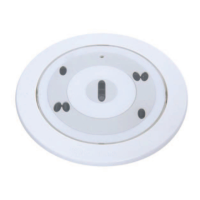
Figure3.8: Rotary switches
Position Description Position Description
CL LSN classic mode xXx Tens
Xxx Hundreds xxX Ones
When connecting the detectors to the LSN fire panels BZ500 LSN, UEZ2000LSN or
UGM2020, all detectors have to be addressed by CL00.
When connecting the detectors to the Modular Fire Panel FPA1200/FPA‑5000, the address
allocation is done automatically or manually.
In case of a manual allocation, all detectors of the same loop, stub or T‑tap have to have an
address between 001 and 254. Addresses between 255 and 299 are not allowed and produce
a fault message on the fire panel.
If the addresses shall be allocated automatically by the fire panel, all detectors must have the
address 000.
Address Operating mode Fire Panel
CL 0 0 Loop/stub in classic LSN mode BZ500LSN
UEZ2000LSN
UGM2020
FPA 1200
FPA 5000
0 0 1 - 2 5 4 Loop/stub/T-tap system in LSN improved mode with
manual addressing
FPA 1200
FPA 5000
0 0 0 Loop/stub in LSN improved mode with automatic
addressing (T-tap system not possible)
FPA 1200
FPA 5000
3.4 Detector and Trim Ring
Notice!
The packaging of the detectors with Csensor consists of tear-resistant PE‑ALU laminated film
and must be cut open carefully.
Do not remove the protective film until the detector is ready to be fitted.
 Loading...