Automatic Detectors LSN improved Maintenance and Service | en 25
Bosch Sicherheitssysteme GmbH Operation Guide 2019.11 | 4.0 | F.01U.025.877
5.3 Inspection Procedure for FAP‑OC520
5.3.1 1. Alternative
1. On the central unit, switch the detector zone to be inspected into test mode. This
automatically sets the detector into revision operation and readies it for the detector test.
Only in revision operation the detector’s individual sensors will trigger with the
corresponding test device. For an alarm, all sensors must trigger at the same time. The
Csensor is triggered using COtest aerosol, the Osensors by being covered up. No
Otesting gas is required.
2. Now hold the test device under the detector so that the test beaker is flush with the trim
ring and seals it tightly.
Make sure that the test beaker does not tilt, which could cause the detector to be lifted
up and consequently become detached from its fastening.
3. Spray the CO testing gas for approximately 1sec.
The test head must remain over the detector until the detector has been triggered.
Distribution of the COtesting gas in the test head and therefore the sensor trigger time
can take up to 20sec.
4. Both scattered light areas are covered by the test beaker, so that both optical sensors are
also triggered at the same time.
5. The detector triggers the alarm and the red alarm LED flashes.
5.3.2 2. Alternative
The detector can be tested in normal operation if a test device with magnet is used.
Notice!
Make sure that the alarm cannot be passed on to higher-level systems. Programmed
activations of the central unit are retained and are executed.
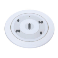
The figure shows the position of the reed switch (Pos.R) in the case of OC detectors.
If you imagine the COsensor (Pos.CO) to be in a 12 o’clock position, the reed switch (Pos.R)
is located at approximately 2 o’clock.
Figure5.1: Position of reed switch
1. Bring the magnet close to the reed switch.
2. The LED of the detector flashes green once a second as soon as the reed switch has been
triggered. The detector will now remain in test mode for 60sec with automatically set
test parameters (e.g. reduction of the delay time to 15sec). The green LED flashes for as
long as the detector remains in test mode.
3. Now hold the test device under the detector so that the test beaker is flush with the trim
ring and seal it tightly.
 Loading...