Interior components diagram and parts list
940 ES – 6 720 644 930 (2019/09)
74
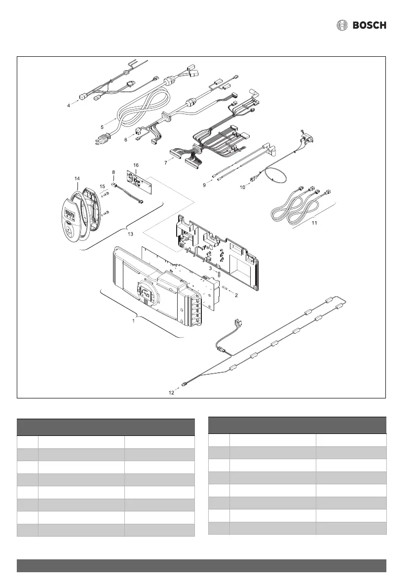
13.2.6 Group 6
Fig. 74 Components Diagram
Table 47
6720644956-09.1V
Item Description Reference
1 Control unit 8 738 708 386
2 Fuse T2.5A 1 904 521 342 0
3 Fuse T1.6A 8 700 609 008 0
4 Power supply cables 8 704 401 371 0
5 Power supply cord 8 704 401 378 0
6 Fan cables 8 704 401 347 0
7 Wire harness 8 738 701 757 0
8 Cable 8 704 401 244 0
9 Electrode cables 8 704 401 346 0
10 Flue gas limiter 8 700 400 032 0
11 Kit inteligent cascading 7 709 003 962
12 Freeze prevention kit 7 709 003 665
13 Remote control (optional) TSTAT2
14 Shaped seal (optional) 8 700 201 012 0
15 Screw (optional) 8 703 401 109 0
16 Printed circuit transceiver 8 708 300 123 0
Item Description Reference
 Loading...