14* Off On On On Off Off
15* On On On On Off Off
16* Off Off Off Off On Off
Table 4.2: Keypad Address Settings
* AMAX 4000
** AMAX 3000 / 3000 BE / 4000
Figure 4.1: 6-Position DIP Switch
DIP switches 5 and 6 are not used.
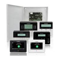
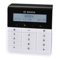
Address setting for IUI-AMAX-LED8 and IUI-AMAX-LCD8 Keypads
IUI-AMAX-LED8 and IUI-AMAX-LCD8 keypads can be set only to address 1 or address 2 through
the address jumper.
Address 1
Jumper not short-circuited
Address 2 Jumper short-circuited (both metal pins are covered)
Table 4.3: Keypad Jumper Settings
Wiring
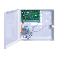
The following graphic shows how to wire a keypad to the option bus of the AMAX panel. The
last keypad must be placed within a cable distance of 200m.
AMAX 3000 BE / 4000
Y
R
Y
G
B
AMAX 2100 / 3000
Keypad
R
B
G
R
B
G
Y
Figure 4.2: Connecting a keypad to the AMAX Panel
4.2.3
AMAX panel Optional Modules and Peripheral Devices | en 15
Bosch Sicherheitssysteme GmbH Installation Manual 2015.05 | 06 | F.01U.309.277
 Loading...