Figure 5.1: 6-Position DIP Switch
DIP switches 5 and 6 are not used.
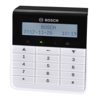
Address setting for IUI-AMAX-LED8 and IUI-AMAX-LCD8 Keypads
IUI-AMAX-LED8 and IUI-AMAX-LCD8 keypads can be set only to address 1 or address 2 through
the address jumper.
Address 1 Jumper not short-circuited
Address 2 Jumper short-circuited (both metal pins are covered)
Table 5.3: Keypad Jumper Settings
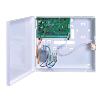
Wiring
The following graphic shows how to wire a keypad to the option bus of the AMAX panel. The
last keypad must be placed within a cable distance of 200m.
Figure 5.2: Connecting a keypad to the AMAX Panel
Notice!
The maximum number of keypads to be added to one option bus is 8.
Status Indicator
If all indicators of the keypad are flashing, the keypad loses connection to the AMAX panel.
5.2.3
5.2.4
AMAX 2100 / 3000 / 4000 Optional Modules and Peripheral Devices | en 15
Bosch Sicherheitsysteme GmbH Installation Guide 2014.11 | 02 | F.01U.267.112
 Loading...