6
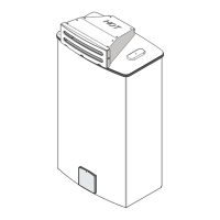
Fig. 3 - Incandescent Particle Tray Illustration
The incandescent particle tray (shipped loose in the carton
with the water heater) must be attached at the bottom of
the water heater front cover at the time of installation. Use
the screws provided. See figure 3.
SCREWS
INCANDESCENT PARTICLE TRAY
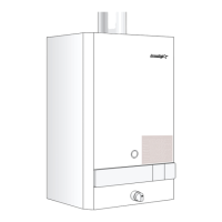
Fig. 2 - Mounting the Heater
WALL STUDS
1 X 4
SPACE BOARD
SUPPORT BOARD
13 ¼
VENTING
WARNING: Do not reduce the vent pipe size.
This appliance must be vented horizontally to the outside
with sealed single wall vent pipe following all local ordinances
and specifications for installing a power vented Category III
appliance. The vent system must be installed by a qualified
installer in accordance with all applicable local gas codes.
The venting system must be designed and constructed so
as to develop a positive flow adequate to remove flue gases
to the outdoors.
CAUTION: Aquastar power vent system must be installed
by a qualified agency in accordance with these instructions.
If improperly installed a hazardous condition such as an
explosion or Carbon Monoxide poisoning could result.
Controlled Energy Corporation will not be responsible for
improperly installed appliances.
Plan the vent system so that code and manufacturers
clearances are maintained.
The minimum clearance from the top of the heater is 12
inches. Single wall vent pipe requires a 3-inch clearance
from combustibles. In all cases, follow local codes:
- In Canada, CAN/CGA-B149 Installation Code for detailed
requirements.
- In USA, ANSI Z223.1 latest edition, National Fuel Gas
Code for detailed.
Minimum vent size diameter must be 4. The appliance
must be located as close as practicable to a vent terminal.
Maximum vent length is 15 feet (4.6m) with two 90-
degree elbows. This unit may be directly connected to
an approved vent termination with a 90-degree elbow. The
vent pipe connections must be secured to each other with
a minimum of 4 sheet metal screws per connection, and
all seams must be sealed with an approved high temperature
silicone sealant and aluminum duct tape. The vent system
must be gas tight. See Fig 4 for suggested venting
installation diagrams.
For best results, the horizontal vent system should be as
short and straight as possible. Vent pipe must be single
wall galvanized steel or stainless steel vent pipe. The
maximum horizontal length of vent pipe is 15 feet. 2
elbows are allowable within this maximum vent
length. For each additional elbow deduct 5 feet from
maximum vent length. Any vertical portion of the vent
pipe that is part of the horizontal vent system must be
considered part of the allowable 15 foot maximum.
When the horizontal vent run exceeds 5 feet the following
criteria must be observed:
- Support the vent run at 4-foot intervals with overhead
hangers.
- Horizontal sections of vent connectors must rise ¼
for every foot of horizontal length. Any vent section
greater than 45 degrees from vertical is considered
horizontal.
Note: Single wall vent pipe cannot be used in any
concealed locations and should not be used in any unheated
space without an insulated chase. Unsealed 5 B-Vent may
be used as a chase for straight lengths (no elbows) of 4
single wall vent pipe. All connections of the 4 single wall
vent within the 5 B-Vent must be properly sealed. A 1
clearance is required from the B-Vent pipe to combustibles.
Freeze Warning:
As mentioned on Page 5, negative air pressure in cold
climates will cause a reverse airflow in the vent system
that can freeze and damage the Aquastar heat exchanger
when not in use. To prevent this the FX Hood vent
terminator, which should have been acquired separately
with the water heater, needs to be installed on the end of
the horizontal vent run (see page 7). The FX Hood is an
approved vent terminator for the Aquastar 125FX and has a
built in back draft flapper.
Spill Switch Safety:
The 125FX is equipped with a Spill Switch; its mounted on
the left side of the draft diverter (Flue gas safety device - #9
on page 19). Before leaving the installation site verify proper
Spill Switch operation by temporarily blocking termination
outlet. The unit will shut down when flue gases are blocked.
You must reset the electrical power to the heater after this
safety test has been conducted, otherwise the unit will not
operate.
 Loading...