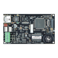
LINK (yellow) LED pattern 100Mb (green) LED pattern Function
Flashing
OFF
10Base-T activity
ON Steady ON Steady
100Base-TX link
Flashing
ON Steady
100Base-TX activity
Table 6.3: Ethernet Link LEDs descriptions
Refer to B426 module overview, page 8 for Ethernet link LED descriptions.
Show the firmware version
To show the firmware version using an LED flash pattern:
– If the optional tamper switch is installed:
With the enclosure door open, activate the tamper switch.
– If the optional tamper switch is NOT installed:
Momentarily short the tamper pins.
When the tamper switch is activated (closed to open), the heartbeat LED stays OFF for 3 sec
before indicating the firmware version. The LED pulses the major, minor, and micro digits of
the firmware version, with a 1 sec pause after each digit.
Flashing patterns do not start until the tamper is open (short is removed). The following is an
example: The version 1.4.3 would be shown as LED flashes:
[3 second pause] *___****___*** [3 second pause, then normal operation].
Figure 6.1: Firmware LED flash patterns example
6.1
28 en | Maintenance and troubleshooting LEDs
Conettix Ethernet Communication
Module
2013.08 | 02 | F.01U.281.208 Installation and Operation Guide (UL) Bosch Security Systems, Inc.

 Loading...


