3 | Installation
1 | Overview
2.1 | Access the address switches
3.4 | Wire to the control panel
After you set the address switches for the proper address,
follow the steps below to install the keypad.
Mounting the mounting plate on the wall:
1. Use the mounting plate as a template to mark the wall
for mounting screw locations, a wire opening, and a level
line.
2. Use the supplied mounting hardware to mount the
mounting plate to the wall.
3. Pull the wiring through the wire opening.
Figure 3.1: Mounting the mounting plate
3.1 | Mount the mounting plate
When you wire the keypad to a control panel, use the control
panel terminals labeled R, Y, G, B (PWR, A, B, COM). Refer to
Figure 3.2.
Callout ― Description
1 ― Control panel
2 ― Terminal wiring
3 ― Keypad’s wiring terminal block
1
2
3
R Y G B
1 COM 2 3 COM COM AUX R Y G B
PWR A B COM
3 COM 41 COM 2
R Y G B
AUX
- 12 V +
1 k End of Line Resistors
3.7 - 5.0 VDC
2.0 - 3.0 VDC
0.0 - 13 VDC
Open
Normal
Short
5 COM 6
R Y G B
PWR A B COM
Figure 3.3: Installing multiple keypads using the
SDI2 terminals
Figure 3.2: Wiring the keypad to the SDI2 bus connection
(B5512 control panel shown)
1 COM 23 COM COM AUX R Y G B
PWR A B COM
3 COM 41 COM 2
R Y G B
AUX
- 12 V +
1 k End of Line Resistors
3.7 - 5.0 VDC
2.0 - 3.0 VDC
0.0 - 13 VDC
Open
Normal
Short
5 COM 6
After wiring the keypad, mount it onto the mounting plate
by seating the mounting hook openings over the mounting
hooks and then sliding the keypad down.
Apply power to the system and test for proper operation.
3.5 | Mount the keypad
CAUTION!
Remove all power (AC and battery) before making
any connections. Failure to do so might result in
personal injury and/or equipment damage.
You can connect keypads to the SDI2 data bus by parallel wire
run from the control panel to each keypad, wire from keypad to
keypad, or a combination of the two techniques.
Refer to Figure 3.3.
2 | SDI2 address switches
Address switches determine the address for the keypad. The
control panel uses the address for communications. Use a
ballpoint pen to set the switches.
1
2
Figure 2.1: Removing mounting plate from keypad
1 2 3 4 5 6
ON DIP
The keypads have 6 DIP switches that support SDI2
addresses 00 to 32. Use the switches to set the keypad
address per the control panel configuration.
If multiple SDI2 keypads reside on the same system, each
SDI2 keypad must have a unique address. Figure 2.2 shows
the address switch setting for address 01. Refer to Table 2.1
for keypad address settings for address 00 to 32.
2.2 | Set the keypad address
Removing the mounting plate from the back of the keypad:
1. Insert a slotted screwdriver under the retention clip to
release it. Do not pry upwards. Refer to Figure 2.1.
2. With your other hand, slide the mounting plate towards
the bottom of the keypad to unhook the mounting plate
from the keypad. Refer to Figure 2.1.
3. Remove the mounting plate.
Figure 2.2: Address switches
Table 2.1: Address switch settings
SDI2
Address
DIP Switches ON
SDI2
Address
DIP Switches ON
1 2 3 4 5 6 1 2 3 4 5 6
00 17 X X
01 X 18 X X
02 X 19 X X X
03 X X 20 X X
04 X 21 X X X
05 X X 22 X X X
06 X X 23 X X X X
07 X X X 24 X X
08 X 25 X X X
09 X X 26 X X X
10 X X 27 X X X X
11 X X X 28 X X X
12 X X 29 X X X X
13 X X X 30 X X X X
14 X X X 31 X X X X X
15 X X X X 32 X
16 X
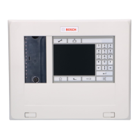
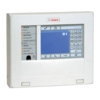
Figure 1.1: Keypad base overview
The B915 and B915I keypads are SDI2 bus devices. The
keypads connect to the bus using terminal wiring. You can
connect more than one keypad to the control panel by wiring
them in parallel.
You can program, diagnose, and troubleshoot the system from
the control panel keypad as well as remotely through Remote
Programming Software (RPS).
The B915 function keys are labeled in English. The B915I
function keys are labeled with icons.
The keypad display shows two-line system messages.
Users can adjust the keypad display brightness level, and they
can turn the keypad’s nightlight feature on or off.
Users can adjust keypad volume, and they can turn the key tone
(short tone emitted when a key is pressed) on or off.
Callout ― Description
1 ― Tamper switch
2 ― SDI2 wiring terminal block
3 ― Address switches
2
1
3
1 2 3 4 5 6
ON DIP
R Y G B
PWR A B COM
COM Z1
Callout ― Description
1 ― Retention clip
2 ― Mounting plate
3.2 | Install the tamper screw
To provide tamper protection from prying the keypad from the
wall, optionally install a screw into the tamper location.
Refer to Figure 3.1.
3.3 | Wire the keypad
Prior to mounting the keypad on the mounting plate, connect
the wiring to the keypad terminals labeled R, Y, G, B. Refer to
Figure 3.2.