3 | Installation
2.1 | Access the address switches
1 | Overview
Caution!
Remove all power (AC and battery) before making any
connections. Failure to do so might result in personal
injury and/or equipment damage.
Turning the keypad nightlight on or off (control panel version
2.1 or higher):
1. Press [MENU] or press [CMD][8] to open the Main menu.
2. Use [NEXT] to go to the Press 5 for Settings Menu option,
or simply press [5].
3. Use [NEXT] to go to the Press 4 for Keypad Confi g option,
or simply press [4].
4. Use [NEXT] to go to the Press 4 for Nightlight option, or
simply press [4].
5. Use [PREV] or [NEXT] to toggle between the Yes and No
options.
6. Press [ENTER] while viewing the desired option to save the
programming.
7. Press [ESC] to exit the menu.
You can adjust the keypad’s display brightness level, and you
can turn the keypad’s nightlight feature on or off.
Adjusting the keypad display brightness:
1. Press [MENU] or press [CMD][8] to open the Main menu.
2. Use [NEXT] to go to the Press 5 for Settings Menu option,
or simply press [5].
3. Use [NEXT] to go to the Press 4 for Keypad Confi g option,
or simply press [4].
4. Press [1] to adjust the brightness.
5. Use [PREV] or [NEXT] to adjust the brightness level. The
changes apply immediately.
6. Press [ESC] to exit the menu.
4 | Display
After you set the address switches for the proper address,
mount the keypad base, wire to the control panel, and attach
the keypad to the base.
3.1 | Mount the keypad
3.2 | Wire to the control panel
You can surface mount the keypad, or mount it to standard
electrical boxes, including single gang boxes.
Mounting the keypad:
1. Use the base as a template to mark the desired mounting
surface. Refer to Figure 1.1 for mounting hole and wiring
locations.
2. Pull the wiring through the desired wire opening in the
base.
3. Use the appropriate mounting hardware (supplied) to
mount the base to the desired mounting surface. Refer
to Figure 1.1 for mounting hole and wiring locations
.
When you wire the keypad to a control panel, use the control
panel SDI2 terminals labeled R, Y, G, B (PWR, A, B, COM).
Connect them to the keypad terminals labeled R, Y, G, B.
Refer to Figure 3.1.
You can connect keypads to the SDI2 data bus by parallel wire
run from the control panel to each keypad, wire from keypad to
keypad, or a combination of the two techniques.
Refer to Figure 3.2.
Callout ― Description
1 ― Control panel
2 ― Terminal wiring
3 ― Keypad’s wiring terminal block
1
2
3
R
Y
G
B
SDI2
PWR+/R
A/Y
B/G
COM/B
27
28
29
26
e
SDI2
PWR+/R
A/Y
B/G
COM/B
28
29
30
27
e
Figure 3.2: Installing multiple keypads using the SDI2 terminals
Reconnect the keypad to the base by sliding the keypad onto
the base (reverse of Step 2). The keypad automatically locks
onto the base. Apply power to the system.
Figure 3.1: Wiring the keypad to the SDI2 bus connection
(B9512 shown)
SDI2
PWR+/R
A/Y
B/G
COM/B
27
28
29
26
e
SDI2
PWR+/R
A/Y
B/G
COM/B
28
29
30
27
e
R
Y
G
B
2 | SDI2 address switches
Two switches determine the address for the keypad. The control
panel uses the address for communications. Use a slotted
screwdriver to set the switches.
Figure 2.1: Unlocking the keypad
G
A
S
Figure 2.2: Removing the keypad from base
G
AS
Set the address switches per the control panel confi guration.
If multiple SDI2 keypads reside on the same system, each
SDI2 keypad must have a unique address. For single-digit
addresses 1 through 9, set the tens switch to 0. Figure 2.4
shows the address switch setting for address 1.
Callout ― Description
1 ― Address switches
1
2.2 | Set the address switches
.
1. Unlock the keypad by turning the lock counter-clockwise.
Refer to Figure 2.1.
2. Hold the keypad by the base in one hand. With the other
hand, gently push down on the keypad to remove it from
the base. Refer to Figure 2.2.
3. Look at the back of the keypad, and locate the switches.
Refer to Figure 2.3
Figure 2.3: Switches location
Figure 2.4: Address switches
1
2
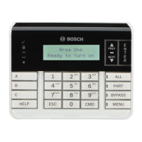
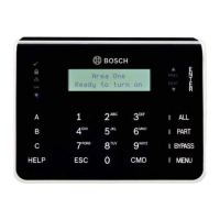
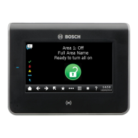
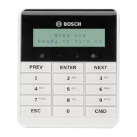
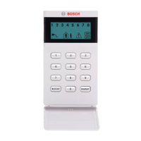
The B925F/B926F keypad is an SDI2 bus compatible device.
Each keypad has an LCD display that shows two-line system
messages, and user adjustable options such as volume and
backlight.
The keypad connects to the SDI2 bus on the control panel
using terminal wiring. You can connect more than one keypad
to the control panel by wiring them in parallel.
You can program, diagnose, and troubleshoot the system from
the control panel keypad as well as remotely through RPS.
Callout ― Description
1 ― Wall mount holes
2 ― Single gang box holes
3 ― Double gang box holes
4 ― Wire opening
5 ― Surface mount wire openings
6 ― Gang box holes (3-4 in)
7 ― Surface mount wire channel
8 ― Bubble level
9 ― SDI2 wiring terminal block
10 ― Wire tie posts
R Y G B
6
2
4
9
1
2
3
3
7 7
5
5
1
1
10
6
6
5
8
10
10
Figure 1.1: Keypad base overview