Do you have a question about the Bosch BVA 2.0 Series and is the answer not in the manual?
Explains warning symbols, keywords, and provides general safety advice for installation.
Details specific risks like electrical shock, fire hazards, and California Proposition 65 warnings.
Covers general positioning, required clearances, and high humidity environment considerations.
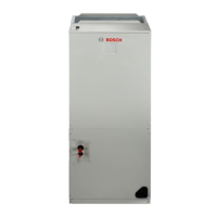
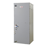
Provides detailed physical dimensions, including height, width, and length, for various air handler models.
Details vertical installation methods and conversion procedures for upflow and downflow.
Explains how to configure the unit for horizontal installation and conversion.
Addresses specific guidelines for installing the unit in unconditioned environments.
Covers general electrical wiring practices, grounding, and control wiring requirements.
Provides electrical specifications, MCA/MOP data, and suitable heat kit compatibility.
Presents SCFM and Watt data for various motor speeds and external static pressures.
Explains two-stage fan control, anti-cold air delay, heating fan delay, and passive dehumidification features.
Covers compliance with fire codes, duct design standards, and material requirements.
Details connecting supply and return ductwork to the unit and ensuring leak prevention.
Outlines steps for sealing, brazing, and insulating refrigerant line connections.
Specifies requirements for condensate drain trap installation and proper drainage.
Discusses filter sizing, placement, and the impact of reduced airflow on system performance.
Warns against operating the unit without filters and potential fire hazards from circulated dust.
Provides detailed dimensions for filter installation and specific filter sizes for models.
Outlines the step-by-step process for removing and installing air filters correctly.
Lists warnings and notices regarding safe cleaning practices and qualified personnel.
Provides a checklist for annual system inspection by a qualified service technician.
Emphasizes safety precautions for wiring, grounding, and power sources during installation.
Illustrates control wiring for 3-Heat/2-Cool thermostats and optional functions as shown in Figure 17.
Shows wiring diagrams for 4-Heat/2-Cool and 3-Heat/1-Cool thermostat configurations (Figures 18 & 19).
Illustrates control wiring for 2-Heat/2-Cool and 2-Heat/1-Cool thermostat configurations (Figures 20 & 21).
Details the wiring diagram for a 2-Heat/1-Cool thermostat configuration (Figure 22).
Provides wire quantities and diameters (AWG) for various system components and models.
Presents a detailed schematic of the indoor unit's internal wiring and component connections.
Explains the function of dip switches and how to set fan speed taps for operation.
| Brand | Bosch |
|---|---|
| Model | BVA 2.0 Series |
| Category | Air Handlers |
| Language | English |