P/N: CM710BIRG Rev 1.3 Page 3
Copyright © 2012 E&OE
Module Address Switches and Output Numbering
Table 2: and Table 3: list the module address settings and corresponding output numbers that apply when adding
output expanders to the listed panels. Each output expander module added to the Solution 16i will provide a maxi-
mum of 4 additional outputs.
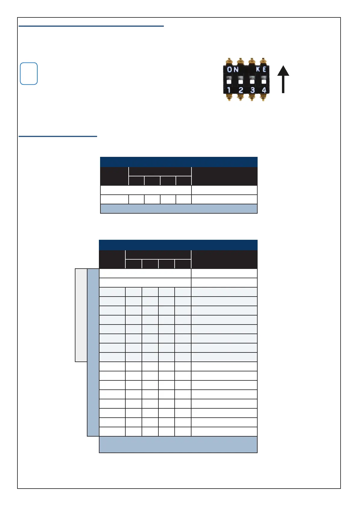
Only one CM710B can be assigned to each address. All mod-
ules are supplied from the factory set to address 1. You must
power cycle the panel or perform a LAN scan whenever you
change the module address. The LAN must be in the unlocked
state or the LAN scan will not find new modules.
Panel Output Assignments
The following tables list the output numbers which become available when adding output expander modules to the
system.
Solution 16i Panel
Module
Number
Address Setting
Output
Numbers
SW1 SW2 SW3 SW4
Control Panel 1 to 4
1 = OFF OFF OFF OFF 5 to 8
1 x CM710B can be fitted to the Solution 16i panel.
Table 2: CM710B Address Configuration On Solution 16i Panel
Solution 144 and Solution E Panels
Module
Number
Address Setting
Output
Numbers
SW1 SW2 SW3 SW4
Solution 144 Panel
Solution E Panel
Control Panel 1 to 5
Virtual Outputs 6 to 8
1 = OFF OFF OFF OFF 9 to 12
2 = ON OFF OFF OFF 13 to 16
3 = OFF ON OFF OFF 17 to 20
4 = ON ON OFF OFF 21 to 24
5 = OFF OFF ON OFF 25 to 28
6 = ON OFF ON OFF 29 to 32
7 = OFF ON ON OFF 33 to 36
8 = ON ON ON OFF 37 to 40
9 = OFF OFF OFF ON 41 to 44
10 = ON OFF OFF ON 45 to 48
11 = OFF ON OFF ON 49 to 52
12 = ON ON OFF ON 53 to 56
13 = OFF OFF ON ON 57 to 60
14 = ON OFF ON ON 61 to 64
15 = OFF ON ON ON 65 to 68
16 = ON ON ON ON 69 to 72
Up to 16 x CM710B can be fitted to the Solution E panel.
Up to 8 x CM710B can be fitted to the Solution 144 panel.
Table 3: CM710B Address Configuration On Solution E and Solution 144 Panels
ON
Position
Figure 1: Address Switch Activation

 Loading...