10 | Boiler information AU/NZ
6 720 646 195a (2010/11)
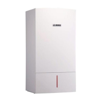
Fig. 4 Additional components
1 Burner ON indicator light (green) 9 PRV pipe connection point
2 Power ON/OFF indicator/fault diagnostic light (blue) 10 CH return isolator
3 Position for optional programmer 11 Gas inlet connection BSP ¾ inch thread
4 Reset button 12 CH flow isolator
5 System pressure gauge 13 Condensate connection
6 ECO button (not used) 14 CH temperature control
7 DHW temperature control* 15 Service mode button
8 Boiler identification label
Tab. 7 Additional boiler components
6720644743-04.1Wo
1 2 3
4 5
6
15
14
91011
13
12
7
8
* The DHW temperature control is only
operational when the “optional internal
diverter valve” is fitted.
 Loading...

