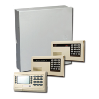
D9412G/D7412G/D7212G Installation & Troubleshooting Quick Reference Guide
D9412G/D7412G / D7212G
Page 23© 2004 Bosch Security Systems, Inc. 43700F
System Wiring Diagrams, Issue A
4.0 System Wiring Diagrams, Issue A
4.1 D9412G Control Panel, 1 of 3
D1640
16.5 V, 40 VA
60 Hz
Transformer
+
AUX PWR
ALARM TRIG
COM
SUPV IN
ALARM CKT
D192A/C/D/G
-
D928
RJ31X
RJ31X
C900
D8132
D126
Battery
12 V, 7 Ah
or
D1218
12 V, 17.2 Ah
or 18.0 Ah
D126
Battery
12 V, 7 Ah
or
D1218
12 V, 17.2 Ah
or 18.0 Ah
D126
or
D1218
- +
D113
BAT 2+
BAT 1+
BAT 2-
BAT 1-
SUPV
CHGR+
CHGR-
VAUX+
-
+
D126
or
D1218
-
+
D126
or
D1218
-
+
D126
or
D1218
EARTH GROUND
COM MON
BATTERY NEGATIVE ONLY
Maximum Charging
Current 1.4 Amps.
BATTERY POSITIVE ONLY
RELAY A
RELAY B
RELAY C
+ AUX POWER
1
2
3
4
5
6
7
8
9
10
CLASS 2 TRANSFORMER
16.5 VAC 40 VA 60 Hz
Model D1640
Inte rnally Fuse d - Do Not short
Requires Unswitched Outlet
Do Not Share With Other Equipment
PROGRAMMABLE
ALARM OUTPUTS
Termi na ls
Requires Optional
Model D136 Relay
In ALT AL ARM
& SW AUX
&
78
GROUND FAULT DETECT
Enabled
Disabled
PHONE
LED
ON WHEN
COMMUNICATING
OFF WHEN IDLE
GRN
PROG
CONN
LOOP START
PHONE MONITOR SELECT
Point 8
GND FAULT
Detect
E
N
A
B
L
E
D
I
S
A
B
L
E
1211 13
Point 1 Point 2
1514 16
Point 3 Point 4
GROUND START
Req uires Rel ay
Model D136 in
Ground
Start Socket
GND START
RED
1
2 3
4 5
7
10
6
8
9
10
10
7
11
10 10
10
16
15
13
7
12
Figure 2: D9412G System Wiring Diagram, 1 of 3
1 - If required by local AHJ, connect D113 Battery Lead
supervision module.
2 - To battery negative
3 - To AUX —
4 - To point input
5 - To battery positive
6 - D8004 Transformer Enclosure required for NFPA
applications.
7 - Optional
8 - D122 Dual Battery Harness, as required
9 - Refer to the D113 Installation Instructions
(P/N: 74-07468-000) for BATT SUPV
10 - Power limited, supervised
11 - Power limited
12 - To Relay A or Relay B
13 - Listed audible signaling devices rated at 10.2 VDC to
13.8 VDC (do not use vibrating type horns).
14 - To RJ31X Jack
15 - 560
Ω
, 2W EOL Resistor (P/N: 15-03130-005)
16 - To earth ground

 Loading...