D9412GV4/D7412GV4/D7212GV4 | Installation and Operation Guide | 11.0 Arming Devices
Bosch Security Systems, Inc. | 3/12 | F01U266054-01 65
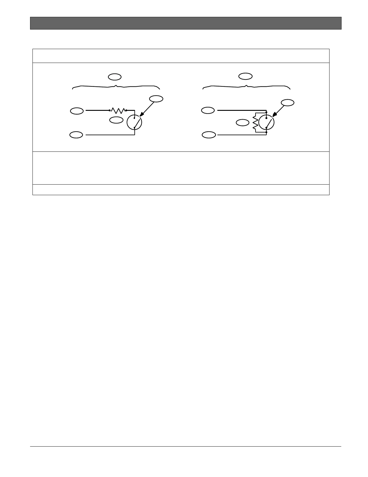
Figure 26: Keyswitch Wiring
1
2
3
4
5
3
4
5
6
7
1 - Maintained keyswitch
2 - Momentary keyswitch
3 - Common
4 - Point input
5 - 1 k
or 33 k
resistor
6- Open on a circuit arms the area
7 - Short on a circuit toggles the arming state
Use 1 kΩ EOL resistors if using one of the zones on the control panel or an OctoPOPIT. Use a 33 kΩ resistor if using a POPIT.

 Loading...


