3.8 Snap the board into the base so the
notch aligns with the tab.
3.9 Select LED operation.
3.11 Microwave range is pre-set. Field adjustment is
not required.
Note: If you choose to adjust the range, set the
adjustment as low as possible for proper catch
performance. Be sure to walk test throughout
the coverage pattern after any adjustment.
3.12 Walk test the detector at the time of
installation and annually thereafter.
3.10 In non-pet applications only, if
look-down is desired, peel away the
look-down mask. Do not remove
the clear plastic lens.
4.0 Coverage Patterns
5.0 FCC Notice
This device complies with Part 15 of the FCC Rules. Operation is subject to the following two conditions:
1. This device may not cause harmful interference.
2. This device must accept any interference, including interference that may cause undesired operation.
Changes or modifications not expressly approved by Bosch Security Systems. Inc. can void the user’s authority to operate the equipment.
3.7 Wire the detector.
LED ON
7.5-9ft
7.5-9ft
7.5-9ft
LED ON
7.5-9ft
7.5-9ft
ON
OFF
7.5-9ft
7.5-9ft
INCREASE
LED ON
7.5-9ft
7.5 -9ft
Peel away
the mask
0
17.5
17.5
350Feet
10.7
0
Meters
10 20 30
5.3
5.3
0
1
2
3
4
5
6
7
8
9
10
11
This detector contains an
environmental stabilization
circuit. After the initial
powerup, the detector needs
approximately 2 min. to
warm up. During this time,
the detector does not
respond to any movement.
Note: Wait 2 minutes after the initial
power-up to perform Walk Tests.
eMicrowav
Coverage
PIR
Coverage
Green = PIR detect
Yellow = MW detect
Red = Alarm
eMicrowav
Coverage
PIR
Coverage
Although generally
not required, if
masking is desired,
the lens diagram
shows the
appropriate areas to
be masked. Use an
opaque material
(such as, electrical
tape) to mask the
desired areas.
DS835i Lens
(inside view)
1 234567891011
12 22
23 33
34 44
45 55
56 66
67 77
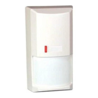
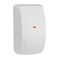
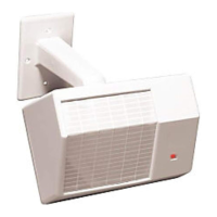
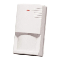
3.6 Mount the detector.
Note: Avoid possible circuit board damage by only
using the mounting hardware that is provided
in the appropriate punch-out mounting holes.
Do not use excessive
force when adjusting the
microwave pot.
Remove
Don't overtighten the mounting screws
Cover may not attach correctly
Corner Mount
Surface
Mount
Thinwall knockouts
for wiring
=
7.5 - 9 ft.
(2.3 - 2.7 m)
Areas
if using the
B335 Bracket
Do not use
the B335
Bracket in
pet
applications
Note: Only use Limited Power
Source up to 5 A maximum.
LED
+
-
6-15
VDC
Alarm
Contacts
Tamper
Contacts
Normally Closed contacts
(DS835iT
only)
35
10.7
0
0
0
310
Meters
Feet
0
10
7.5
Look
Down
67-
77
56-
66
45-
55
34-
44
23-
33
12-
22
1-
11
1/11
DS835i/835iT Installation Instructions
P/N: F01U035203-02 Page 2
© 2011 Bosch Security Systems, Inc.
130 Perinton Parkway, Fairport, New York 14450
www.boschsecurity.com
 Loading...