22 en | Technical Specifications FAS-420-TM Aspirating Smoke Detector
F.01U.088.878 | 4.1 | 2010.11 Operation Guide Bosch Sicherheitssysteme GmbH
Data is transmitted to the diagnostic appliance via the infrared port of the aspirating smoke
detector. The USB cable provided is used to transmit the data from the diagnostic appliance
to the PC/laptop (see Figure 2.15).
Windows 2000 or Windows XP can be used as the operating system. For correct color display,
the monitor and graphics card must be able to display more than 256 colors.
Diagnostic messages remain saved in the FAS-420-TM for at least 3 days in order to be able to
evaluate even short, sporadically occurring errors (e.g. in case of changed operating
conditions). Resetting the FAS-420-TM via the diagnostic software deletes all saved diagnostic
messages. The software also allows the deletion of error messages.
2.5.7 Remote Indicators
A remote indicator must be connected if the aspirating smoke detector is not directly visible
or has been mounted in false ceilings or floors.
The external detector alarm display is installed in an obvious place in halls or entrances of the
building section or areas concerned.
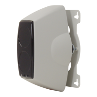
FNS-420-R LSN Strobes can be used as remote indicators. These must be ordered separately.
The FNS-420-R LSN strobes can be addressed and are connected to the LSN bus.
If the FAS-420-TM-R and FAS-420-TM-RVB device variants with fire source identification are
used, the FNS-420-R LSN Strobes can be assigned to the various monitoring ranges and, in
the event of a fire, the location of the fire can be identified.
2.6 Pipe System Components
2.6.1 Overview
NOTICE!
The diagnostic software can be used to save in file format all stored and current diagnostics
data and any settings made via the fire panel programming software. To be able to compare
the data read out, save each file under a different file name.
Figure 2.16 Pipe system components
A Pipe system connection
B Smoke aspiration pipe
1 Connection for test adapter
2T-fitting
3 Air filter
4Water separator
5Detonation safety barrier
(not permitted for EN 54-20)
6 90° pipe bend
7 Aspiration hose for ceiling
lead-through
8 Ceiling Lead-through
9 Fitting
10 Double threaded joint
11 90° pipe elbow
12 45° pipe elbow
13 Aspiration reduction
14 End cap
F
A
S-4
2
0
-
T
M
s
e
r
ie
s
A
A
A
4
5
3
2
7
6
8
9
10
11
12
13
1
14
A
B
 Loading...


