EasyManua.ls Logo

Bosch FPA-5000 - Usage in accordance with regulations; Skills required by personnel

Bosch FPA-5000
178 pages
To Next Page IconTo Next Page
To Previous Page IconTo Previous Page
Loading...
8 en | Product Description Modular Fire Panel
F.01U.028.089 | 8.0 | 2011.07 System Description Bosch Sicherheitssysteme GmbH
System Overview
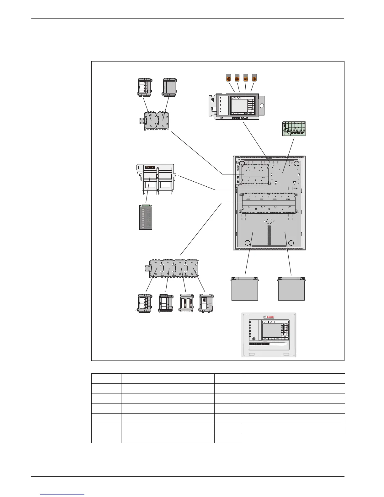
The figure below shows an example configuration:
Figure 2.2 Example configuration
Position Description Position Description
1 Functional modules 7 Power supply unit
2 Address cards 8 Housing (in this case: HCP 0006 A)
3 Panel controller 9 Panel rail, long
4 Distributor, optional (RLE) 10 Batteries
5 Panel rail, short 11 Remote keypad
6 Power supply bracket
N
I
TUO
N
I
TUO
#
0
*
89
56
23
7
4
1
?
PQRS TUVWXYZ
GHI JKI MNO
ABC DEF
Fire
Test
CityTie
CityTie Fault
Ground Fault
Battery Fault
Power
Trouble
Signal Silence
Bypassed
Supervisory
NAC1 NAC
3
NAC
7
NAC
9
NAC5
NAC
2
NAC
4
NAC
8
NAC
10
NAC
6
PS
2
PS3 PS
5
PS
6
PS4
BCBAT
BCBAT
BAT2
10A
25A
25A
Bridge 2- 3 Bridge 3- 4 Bridge 4- 5 Bri d ge 5- 6
-- ---++ +++
-+ -+
-
+
BAT1
A
BAT1
B
-
+
-
+
NETZEIN
NETZSTROM
Srung
BATTERIE1
Srung
BATTERIE2
Srung
FAULT
MAIN
+-
BAT1
+-
BAT2
+-
BAT1
+- +-
FAULT
AC
FAULT
AUX3
+-
AUX4
+-
AUX2
+-
AUX1
+-
AUX5
+-
AUX6
+-
BCM0000A
LSN 0300 A
AU X 1
+-
LSN1
a-b+
AU X 2
+-
LSN2
a-b +
ZONE 4
Störung
ZONE 3
Störung
ZONE 2
Störung
ZONE 1
Störung
CZM0004A
AUX1
+-
OUT1
+-
IN 1
+-
AUX2
+-
OUT2
+-
IN 2
+-
AUX3
+-
OUT3
+-
IN 3
+-
AUX4
+-
OUT4
+-
IN 4
+-
ANI0016A
F2F1
NC1
NO1
C1
NC2
NO2
C2
FB1
+
-
FB2
+-
RELAIS 2
St örung
RELAIS 1
St örung
RMH0002A
OUT3
OUT2
OUT4
OUT6
OUT5
OUT7
GND
OUT8
GND
GND
GND
IN 1
IN 3
IN 2
IN 4
IN 6
IN 5
IN 7
GND
IN 8
GND
GND
GND
OUT1
IOP0008A
3
4
2
5
1
6
7
9
1
10
11
8

Table of Contents

Other manuals for Bosch FPA-5000

Related product manuals