lnfluences
on
Accuracy
The ambient temperature has the
greatest
influence, especially temperature differences
occurring
from
the
ground
upward can
divert
the laser beam.
As thermal
fluctuation is
closest to
the
ground,
if
possible
the tool should be mounted on a
commercially available tripod and
placed
in
the center of
the work area.
Apart from exterior influences
(such
as heavy
impact or falling down) can
lead
to deviations.
Therefore, check
the
accuracy of
the tool each
time before starting
your
work.
First,
check
both the height as well as
the
leveling accuracy of the
horizontal
and
vertical
laser line.
Should
the
tool exceed
the maximum
deviation
during one of the tests,
please
have
it repaired by a
Bosch
after-sales
service.
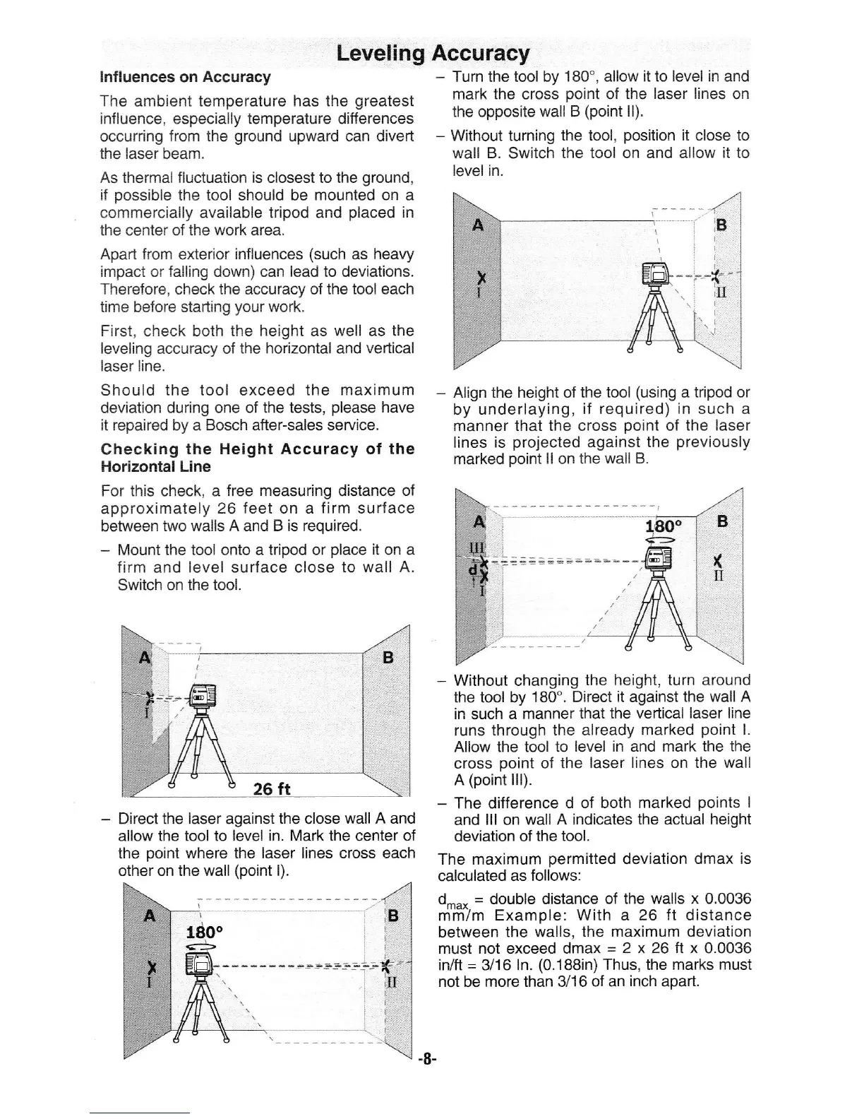
Checking
the Height Accuracy of the
Horizontal Line
For this check, a
free measuring
distance
of
approximately
26 feet on a firm surface
between
two walls A and B is required.
-
lVlount the tool onto a tripod or
place
it
on a
firm and level surface close
to wall A.
Switch on the tool.
-
Direct the laser against the
close
wall A and
allow the
tool
to
level in. Mark the center of
the
point
where the laser lines cross each
other on the
wall
(point
l).
Leveling Accuracy
-
Turn the tool by 180', allow it to level in and
mark the cross
point
of
the laser lines
on
the opposite wall
B
(point
ll).
*
Without turning
the tool,
position
it close to
wall B.
Switch
the
tool
on and allow
it to
level in.
-
Align the height of
the tool
(using
a tripod or
by underlaying,
if required)
in
such a
manner that the cross
point
of the laser
lines is
projected
against the
previously
marked
point
ll
on
the wall B.
-
Without changing
the
height, turn
around
the tool
by
180'. Direct
it
against
the wall A
in such a manner
that the veftical
laser line
runs through the already
marked
poini
L
Allow the tool
to level in and mark the
the
c!"oss
point
of the
laser lines on the
wall
A
(point
lll).
-
The difference
d of both marked
points
I
and
lll on wall
A indicates the actual
height
deviation
of the tool.
The maximum
permitted
deviation dmax
is
calculated
as follows:
d-.,
=
double
distance of the walls
x
0.0036
mm/m Example:
With
a
26 tI distance
between
the walls, the maximum deviation
must not exceed dmax
=
2 x 26 tI x 0.0036
in/ft
=
3/16
ln.
(0.1BBin)
Thus,
the marks
must
not be more than 3i
16 of an inch apart.
-8-
I
iB
I
I
I
-.J
B
,(
il
 Loading...