6 720 608 782
48
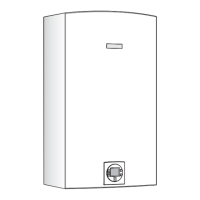
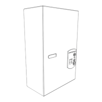
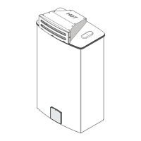
Interior components diagram and parts list
12.2 Components diagram
12.2.1 Group 1
Fig. 65 Components Diagram
9
9
8
5
1
2
3
6
7
9
10
12
9
14
16
17
11
13
15
15
4
6720902973.AA JF
Item Description Reference
1 Front cover 8 705 431 286
2 Cover shield 8 705 506 862
3 Trade mark badge 8 701 103 140
4 Cover screw 8 703 401 170
5 Combustion cover 8 700 506 300
6 Combustion cover gasket 8 704 701 084
7 Observation window 8 705 600 003
8 Holding bracket 8 708 104 103
9 Screw 8 703 403 012
Table 21
10 Combustion cover clip 8 701 201 032
11 Grommet set 8 710 203 039
12 Exhaust accessory 8 705 504 162
13 Gasket exhaust 8 700 103 710
14 Inlet air cover 8 708 006 022
15 Inlet air gasket 8 700 103 166
16 Inlet air accessory 8 705 504 116
17 Mounting bracket 8 701 309 164
Item Description Reference
Table 21
 Loading...