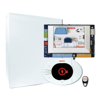
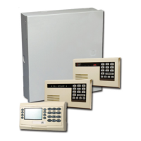
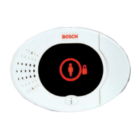
Control Center
Audio Bus Wire Type Options: 1 two-conductor or 1 four-conductor, power-limited 1.2 mm (18 AWG) or 0.8
mm (22 AWG) wire. Only two conductors are used.
At least 0.6 mm (24 AWG) twisted pair CAT5 wire.
UL installations require power-limited wiring.
Unless using CAT5 cable, audio bus connections require a dedicated wire.
CAT5 Wire Requirements: Refer to Install the Control Center, page 26.
Protection Level IP 30 - IK 04
Control Center Display States
Display Color Description
Green circle No alarm or trouble conditions exist.
You can turn on the system.
Flashing green circle System trouble exists. You can still turn on the system.
Alarm memory active.
Flashing amber circle System trouble exists. You cannot turn on the system.
Alarm memory active.
Broken green circle Wired point(s) are faulted. Turn on the system to bypass
faulted point(s).
Chime point faulted. Chime tone sounds.
Broken amber circle Wired point(s) are faulted. You cannot turn on the system.
Broken red circle;
flashing red icons
Fire or intrusion alarm occurred.
Single rotating segment Alarm memory announcement. Add or change user token.
Waiting for information from wireless network.
Green circle and icons Add or change user passcode. Outside icon appears for first
passcode entry.
Inside icon appears for second passcode entry.
Green or amber Point walk test.
Green single circle segments represent tested points.
Green flashing icons Control center test. Icons alternately flash.
Table 8.1: System Off Display States
Easy Series Control Panel Device Specifications and Overview | en 71
Bosch Security Systems, Inc. System Reference Guide 2014.09 | 01 | F.01U.306.221
 Loading...
